Fast forward 20 years
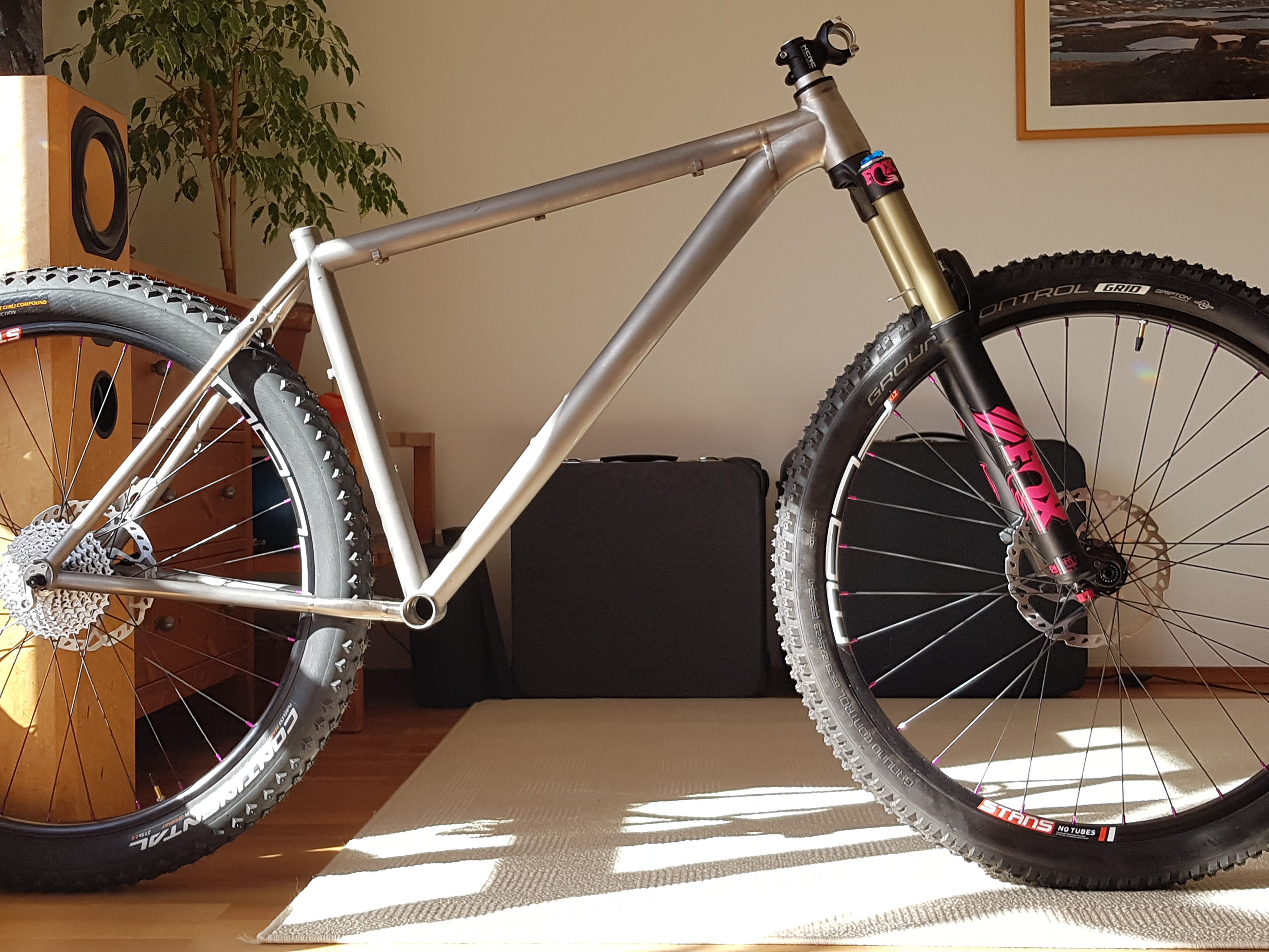
Conversion of a classic mountain bike frame to contemporary wheel size and geometry.
Conversion of a classic mountain bike frame to contemporary wheel size and geometry.
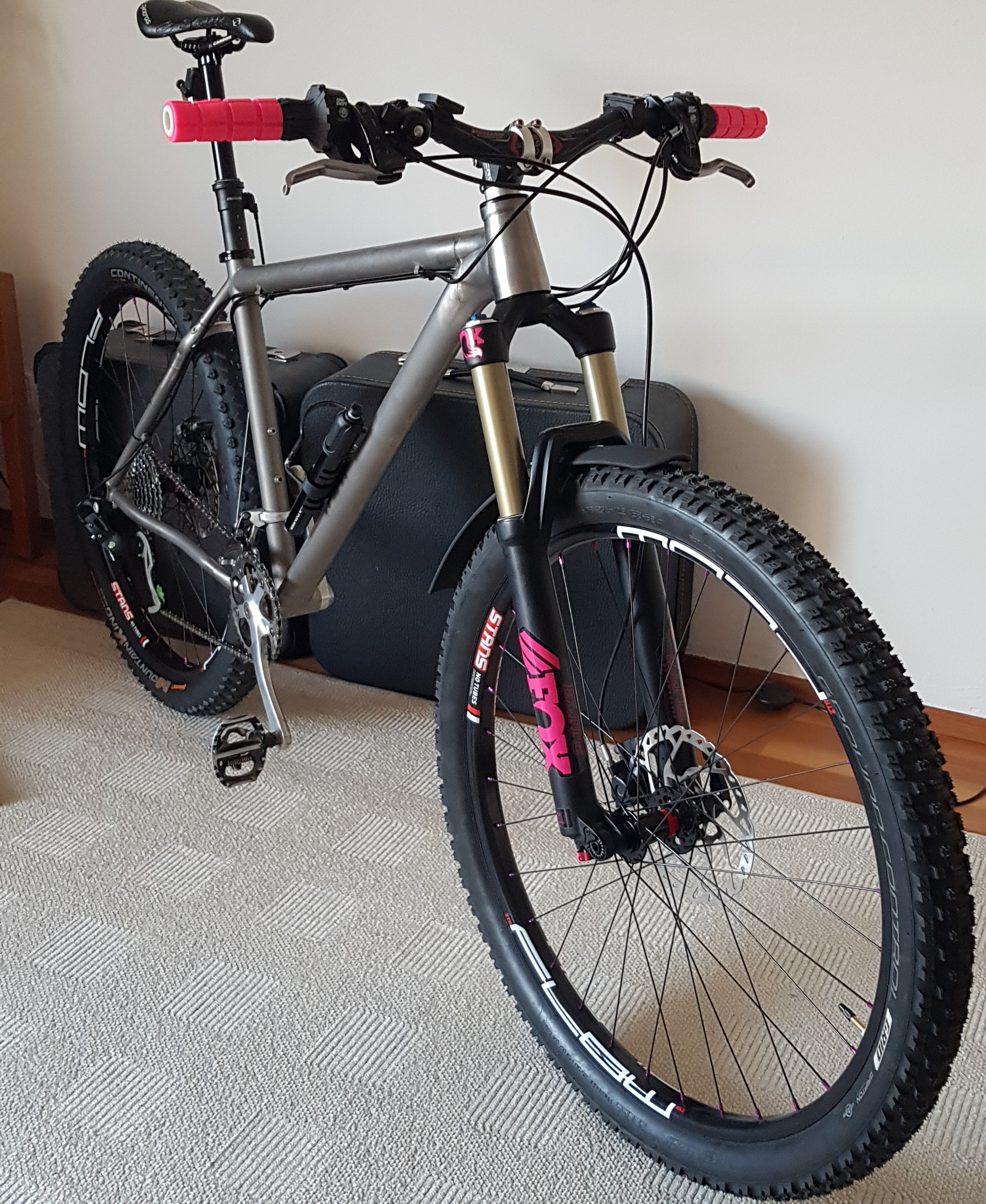
Long story short: In 2020 / 2021 I redesigned a titanium mountain bike frame using 3D printed parts. The project covered a lot of areas, like bike geometry, CAD design, 3D printing/post processing and more.
Result: My all-time favorite bike.
Credits:
EOS for providing the printed parts
Wheeldan for way more than just welding
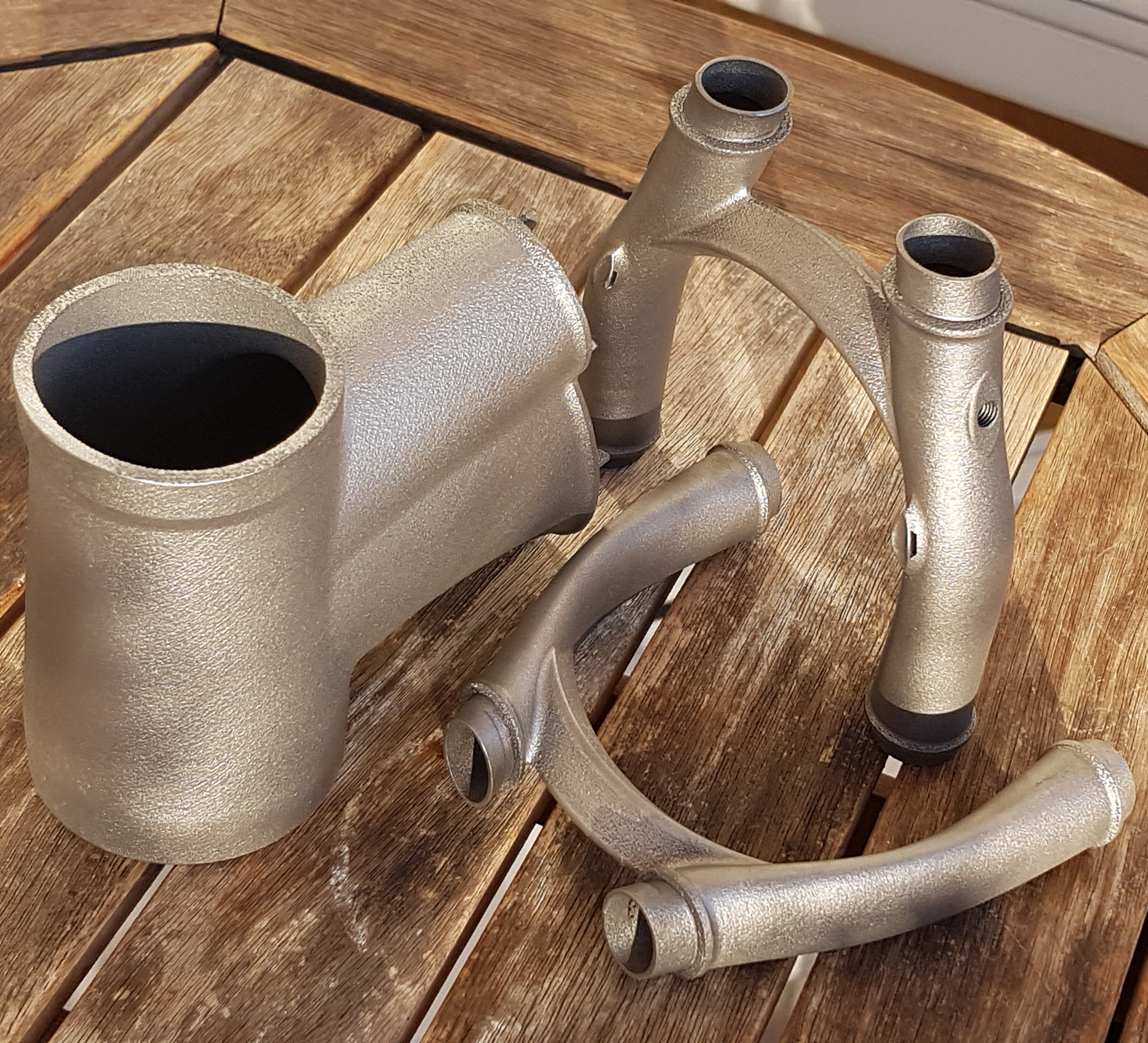
Titanium 3D printing in action
I am a loyal person. With regards to my bikes, I tend to ride them over a long time and keep them running. To some extend, this collides with advancements in bicycle tech - like the advent of disc brakes or new headset standards. I focus on mountain bikes since a long time, and they have seen a lot of development in the last, well, decades already. The changes have been fundamental, suspension travel grew, wheel sizes and geometry changed. I stayed reluctantly in the 26" camp, riding (mainly) hardtail frames, but at the same time eager to try out the cool new toys. This led to retiring frames to rigid fork / commuter use, overforking the next frame with more and more travel, sqeezing in the fattest tires possible ... and having a ton of fun riding these setups all along.
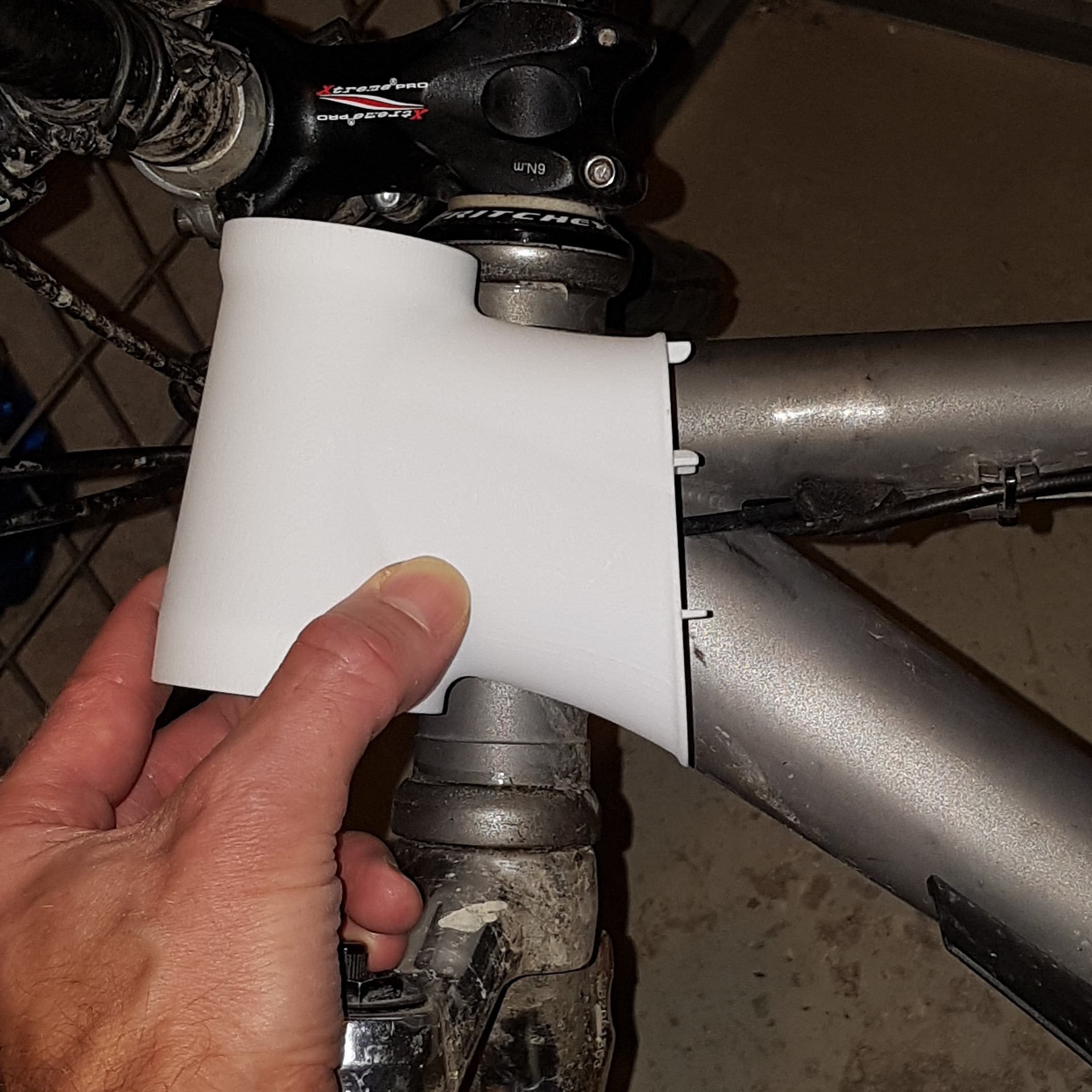
My mountain bike of the 2010 years was based on a lightweight titanium frame, bought on Ebay, "Cube" branded (yes, sorry!), thin-walled, partly ovalized tubes, with a very classic XC 71/73 geometry when equipped with a 100mm fork. Oh, and 26 inch wheels, for sure. As I moved to a sturdy 120mm fork, I noticed that even second hand forks with a straight 1 1/8" steerer got rare. I designed a 3D printed angle correction headset which slackened the head tube angle by 0.9deg - at least. The effect was still very noticeable, and I got even more curious how a really contemporary geometry would ride.
My riding now included small jumps and drops, and I noticed the short wheelbase - thankfully, my few crashes were harmless. I ran 2.8" tires at the time (the plus bike hype was just fading out), and I had to cut the side knobs at the back tire to fit the wheel without much rub.
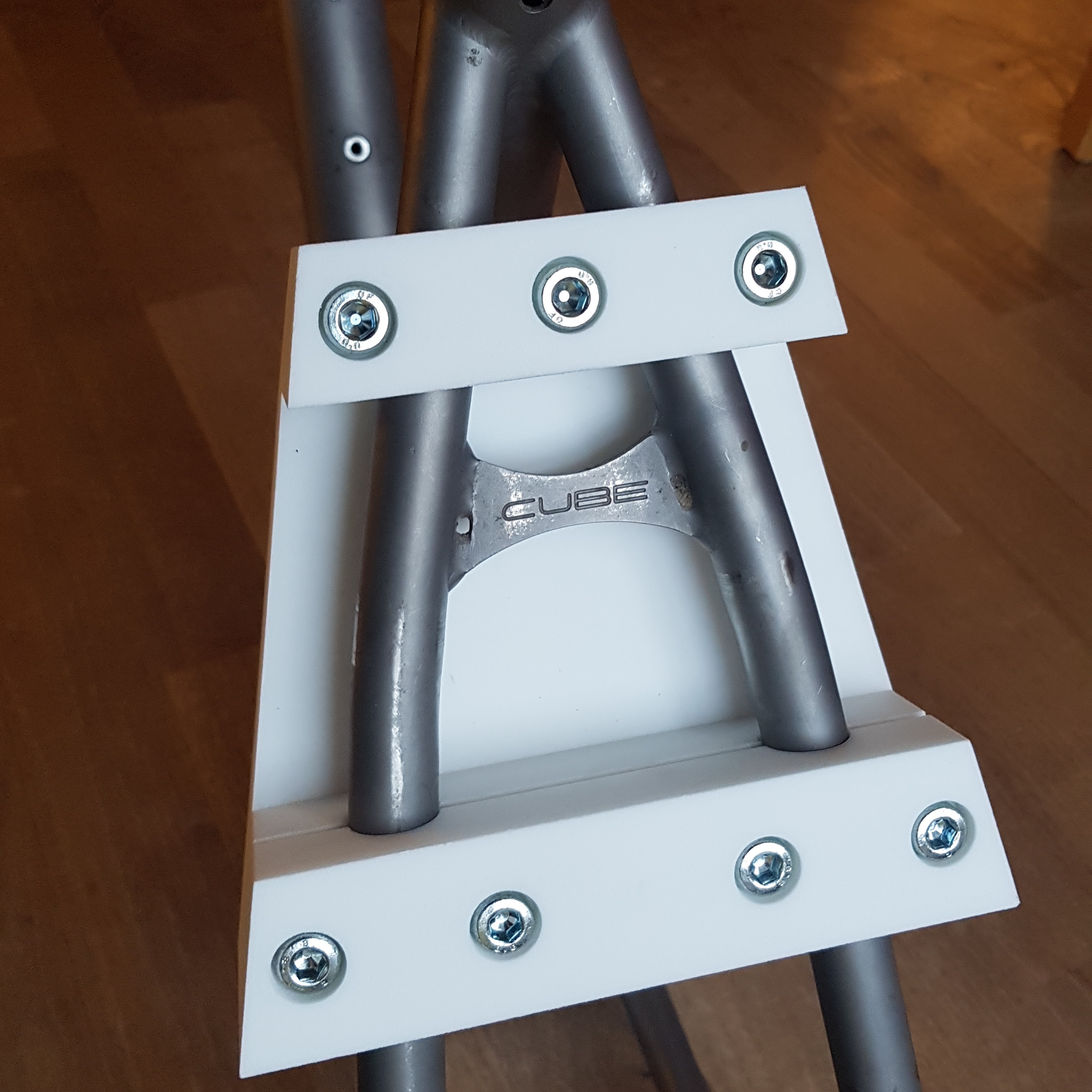
Having access to 3D printing, I came up with a plan: how about cutting off the whole steerer tube section, print an new one with longer, slacker geometry and let a titanium frame builder weld it on? Well, and if this builder would also widen the chainstays and seatstays to make room for a nice fat 27.5" wheel - what a project!
Talking to several frame builders, I learned that it is not a cool idea to try to cut holes in titanium chainstays and seatstays and weld inserts in there. Rather I could design 3D printed sections, why not?
I convinced Daniel, that time still in Berlin, to do the welding. A 140mm 27.5" fork was sourced second hand, and I committed to build the new wheels already.
The design process started with various measurements on the existing bike. Overall geometry figures, cross sections of the ovalized downtube, silhouette of chainstays and seatstays, all went into a 3D CAD model. I had to make educated guesses for the wall thickness of the affected tubes as I wanted to ride my bike until the end instead of cutting the frame to pieces already.
At the core was the new geometry. At this point, I based my choices on my riding experiences with former bikes and on the effects of various modifications, usually "overforking" and fitting angle correction headset cups on several bikes. Of course I was also busy studying geometry charts and reviews online. In 2020, the move to longer and slacker geometry figures was still full on, and I had to keep track and find my sweet spot.
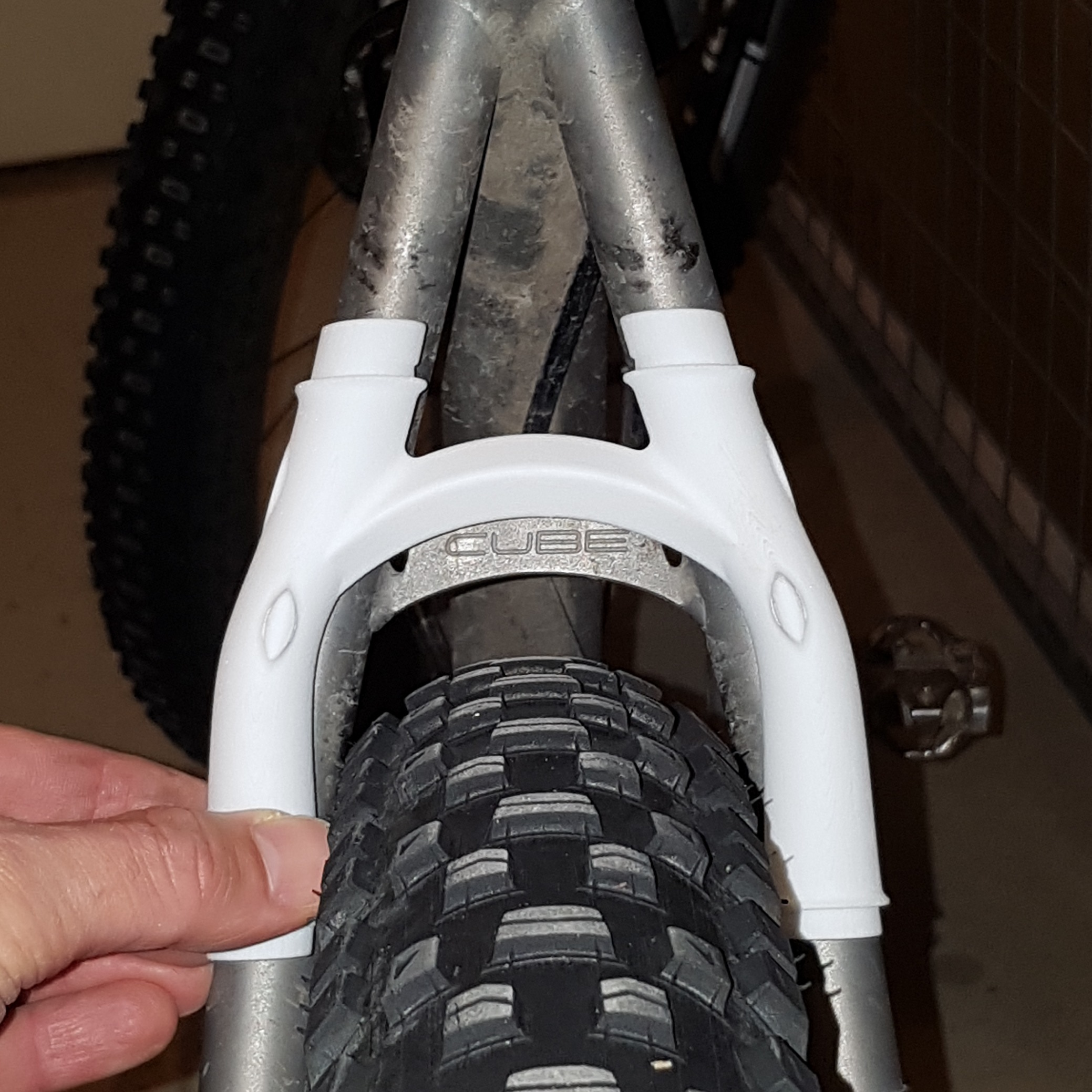
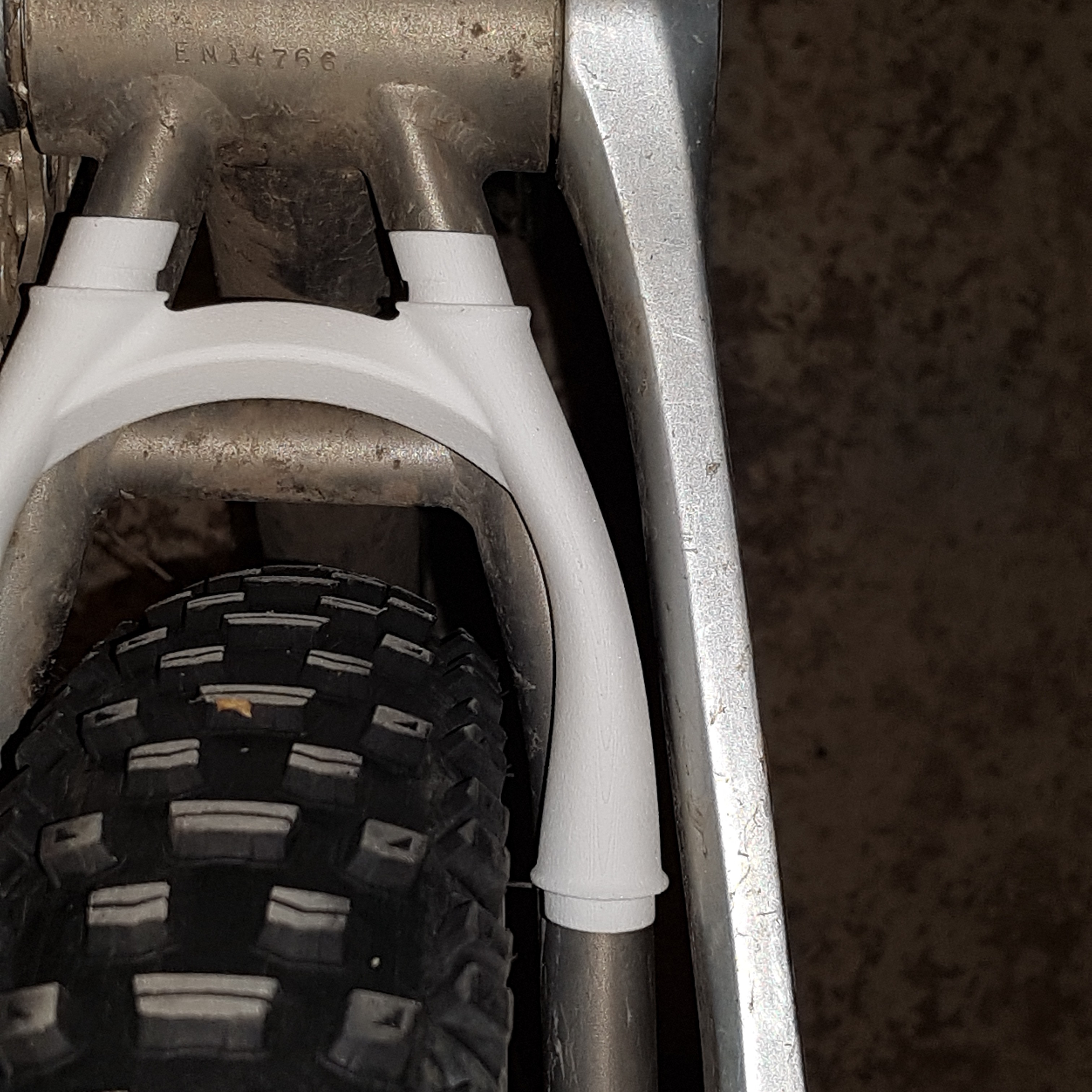
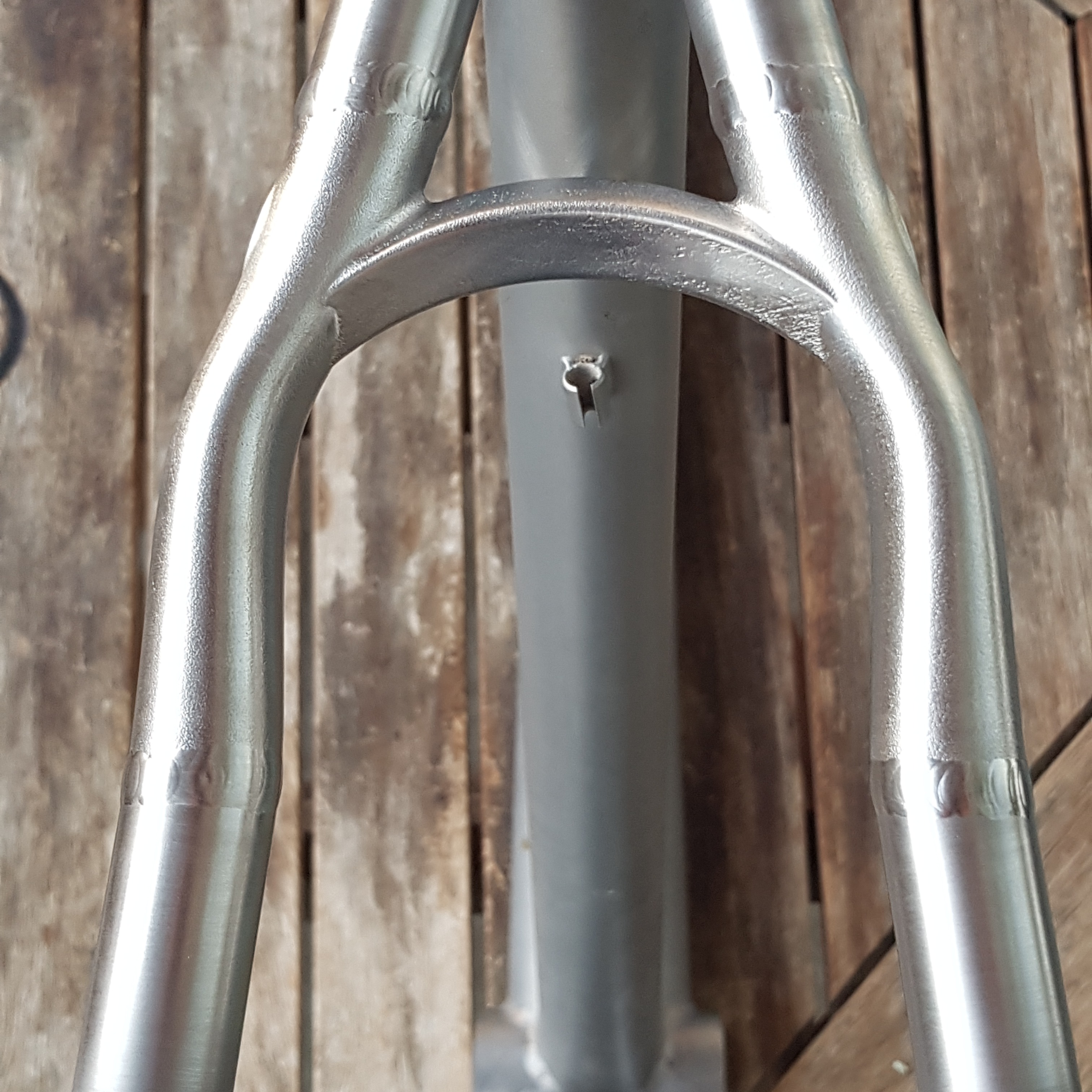
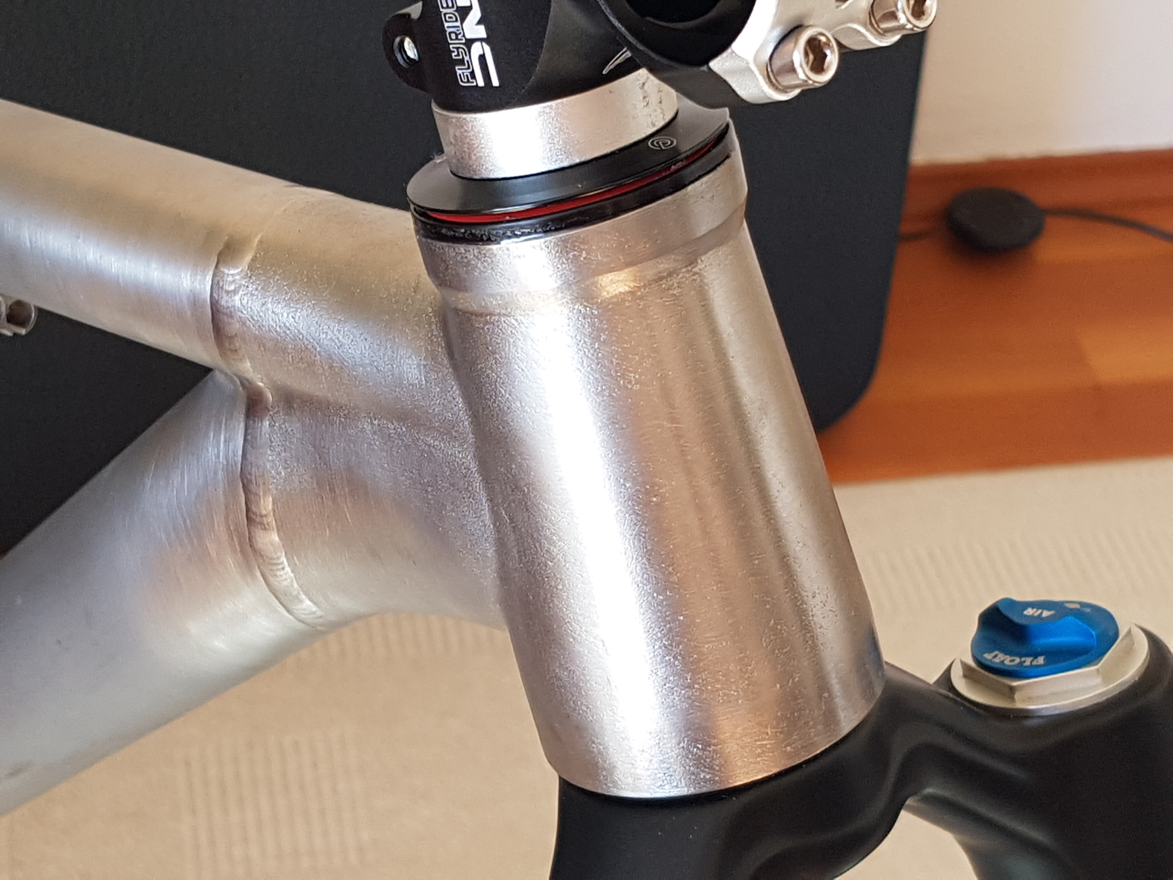
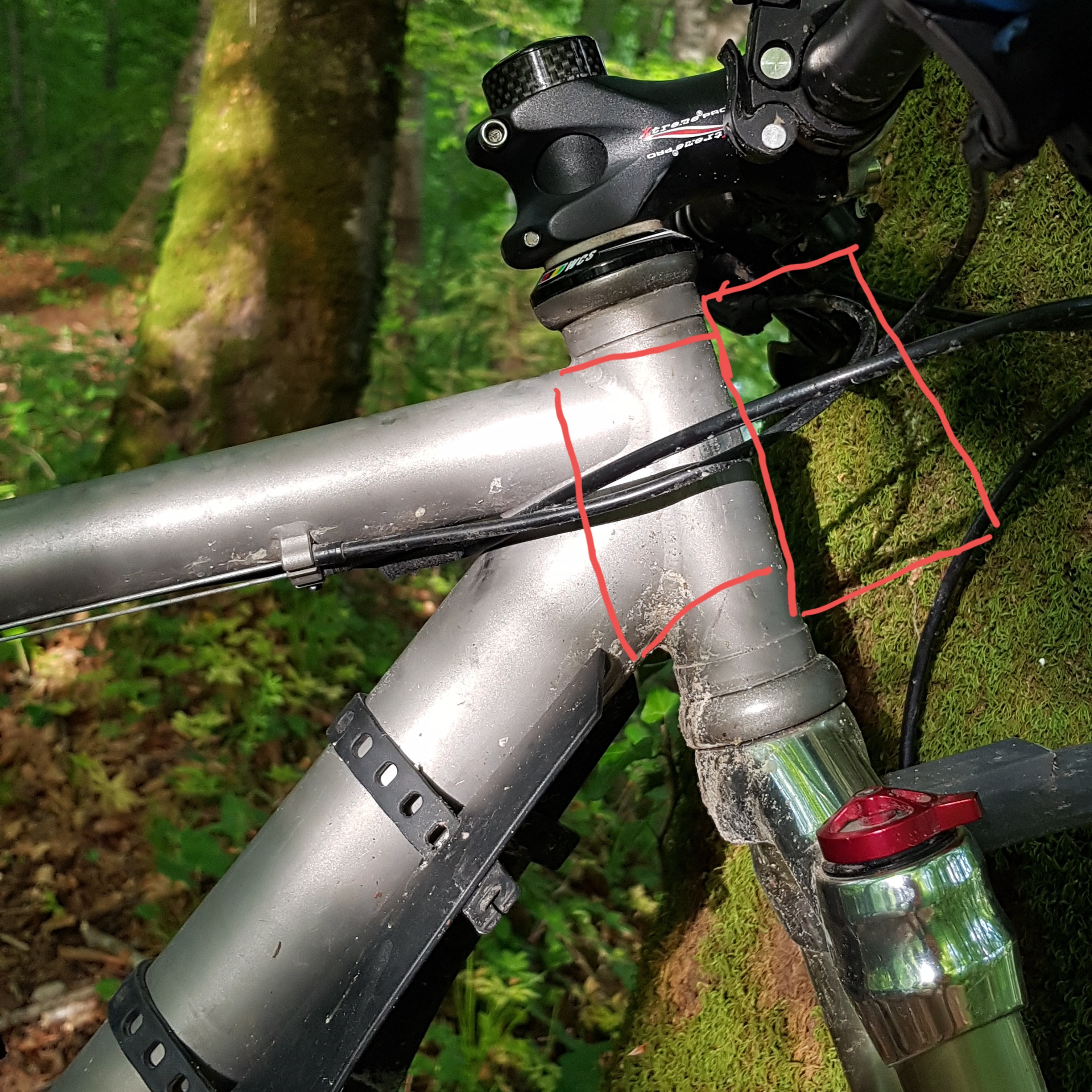
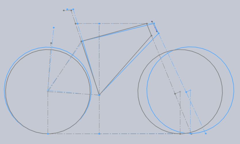
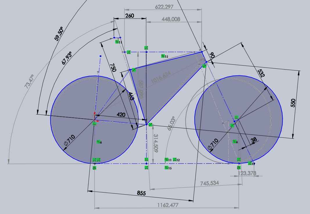
My new fork had the steerer tube cut quite short, so the headtube had to be very short. Good that I like low stack heights anyway! Tapered steerer, obviously. For the headset, I went for a combination of IS52 / ZS44. The most fundamental questions were: what reach? And what head tube angle? The old values were 386mm (yes you read that right, no typo) and 68deg. It felt very progressive to settle on 438mm / 66deg (all values with the fork unsagged). Thankfully, I made a last minute decision to go further: 448mm / 65deg.
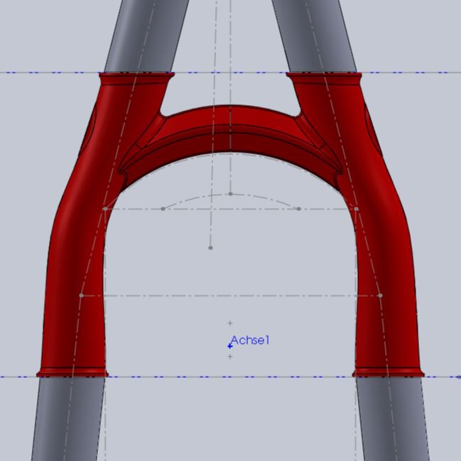
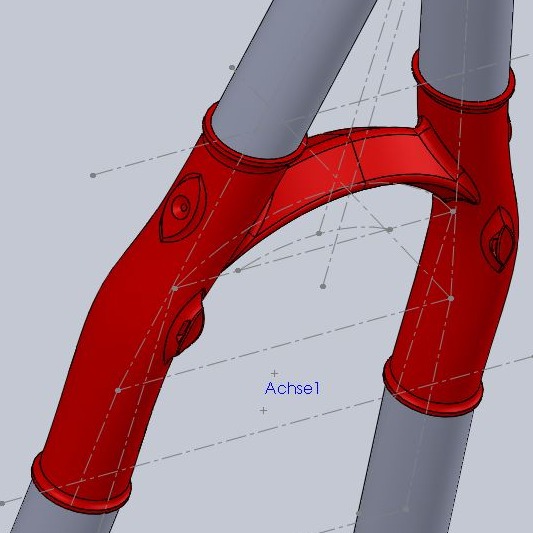
The stack height remained about the same at 587mm and I steepened the seat tube angle from 71.6deg to 73.5deg (also unsagged). Tilting the frame forward also provided an almost unchanged bottom bracket height with the larger wheel radius. The comparison sketch shows the transformation quite nicely. For context, I am about 182cm.
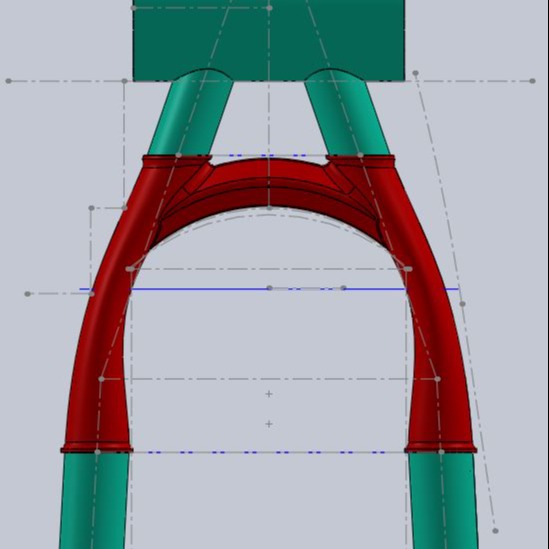
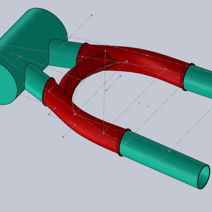
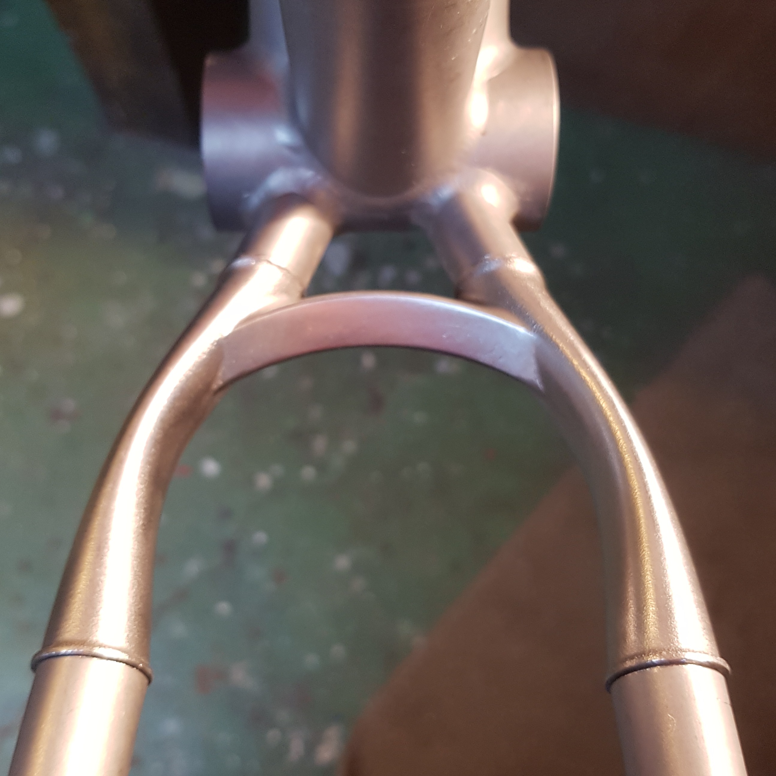
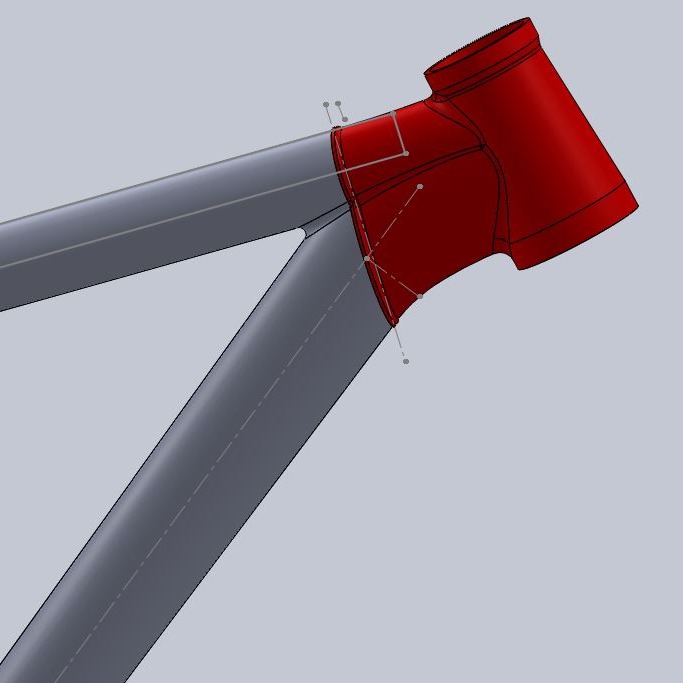
Modelling the steerer unit was nice and satisfying. Things played out very well, as lengthening the frame lifted the lower headset bearing, making room for the longer fork. With the slacker HTA the fork crown did not end up that high anyway. On the contrary, the steeper seat tube angle lowered the front end of the frame, but I ended up with a pleasing aesthetics which I liked way more than the old look.
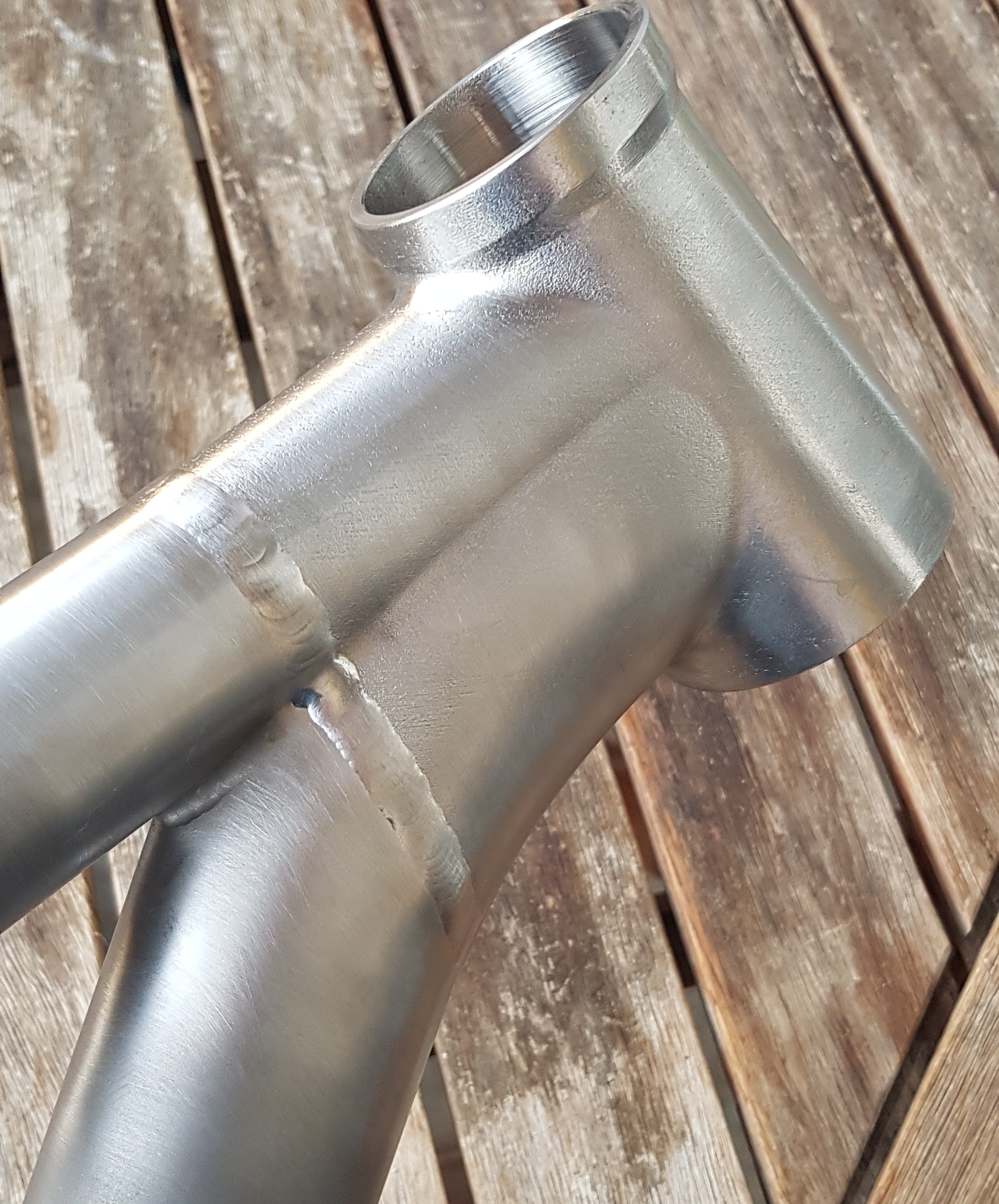
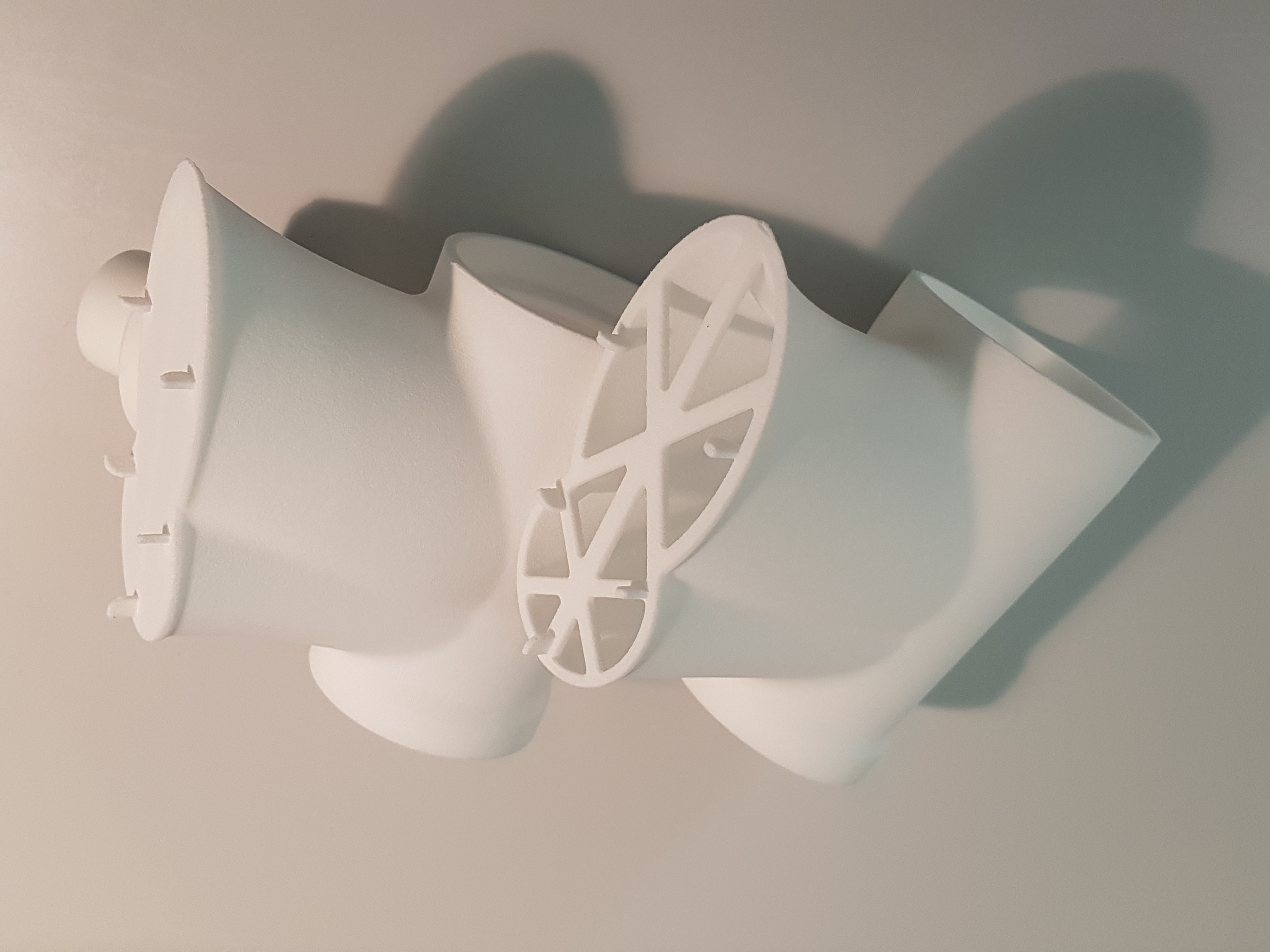
As it is often, the design process started easily, but soon things got more complicated. I settled on a wall thickness which was lightweight, comparable to the old head tube, while still being viable for printing in the DMLS process. There are design constraints regarding the orientation of the part during the build. Overhanging sections need to be supported from some point on, and the support structures must be removed afterwards. This is manual work, and it may be impossible to do this inside hollow structures.
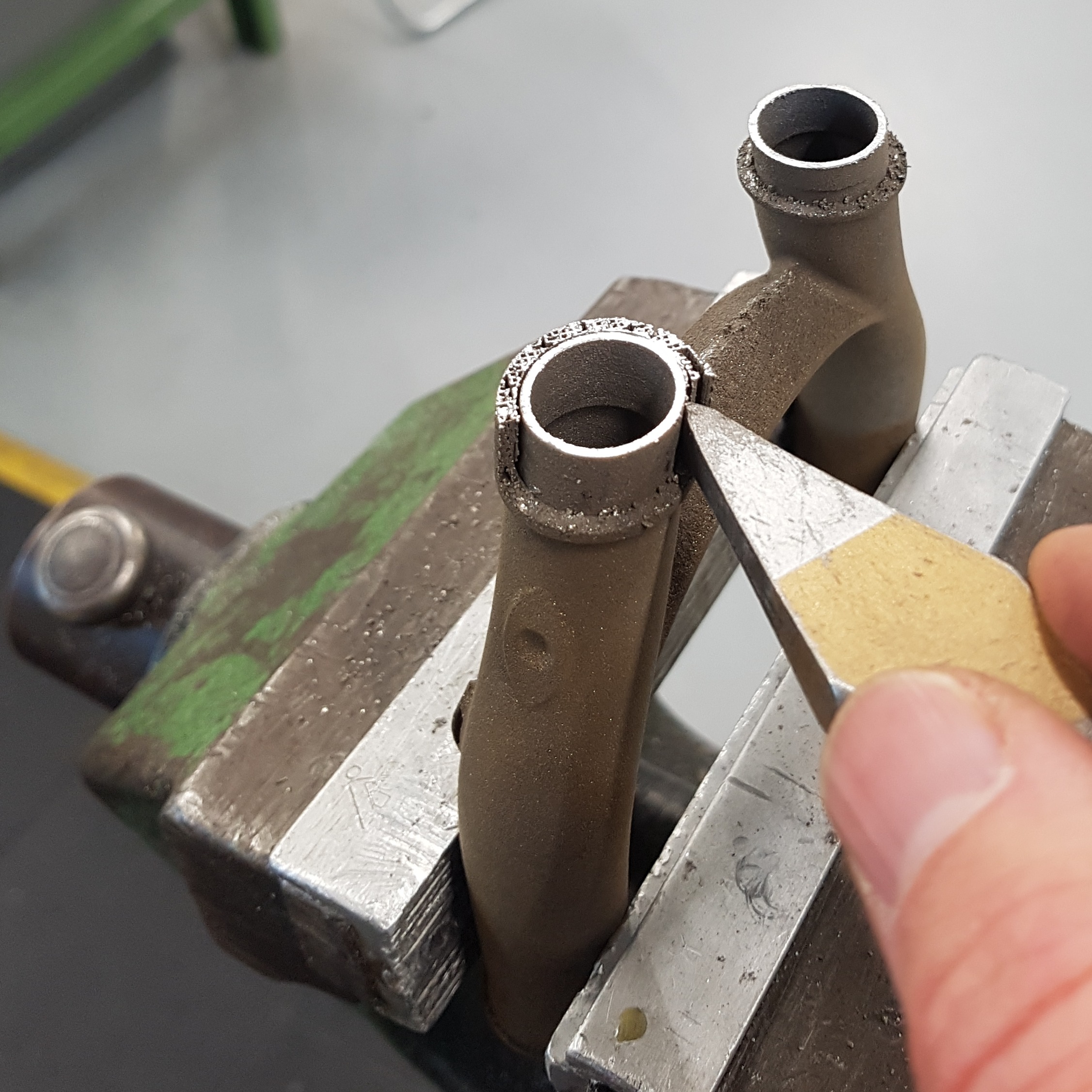
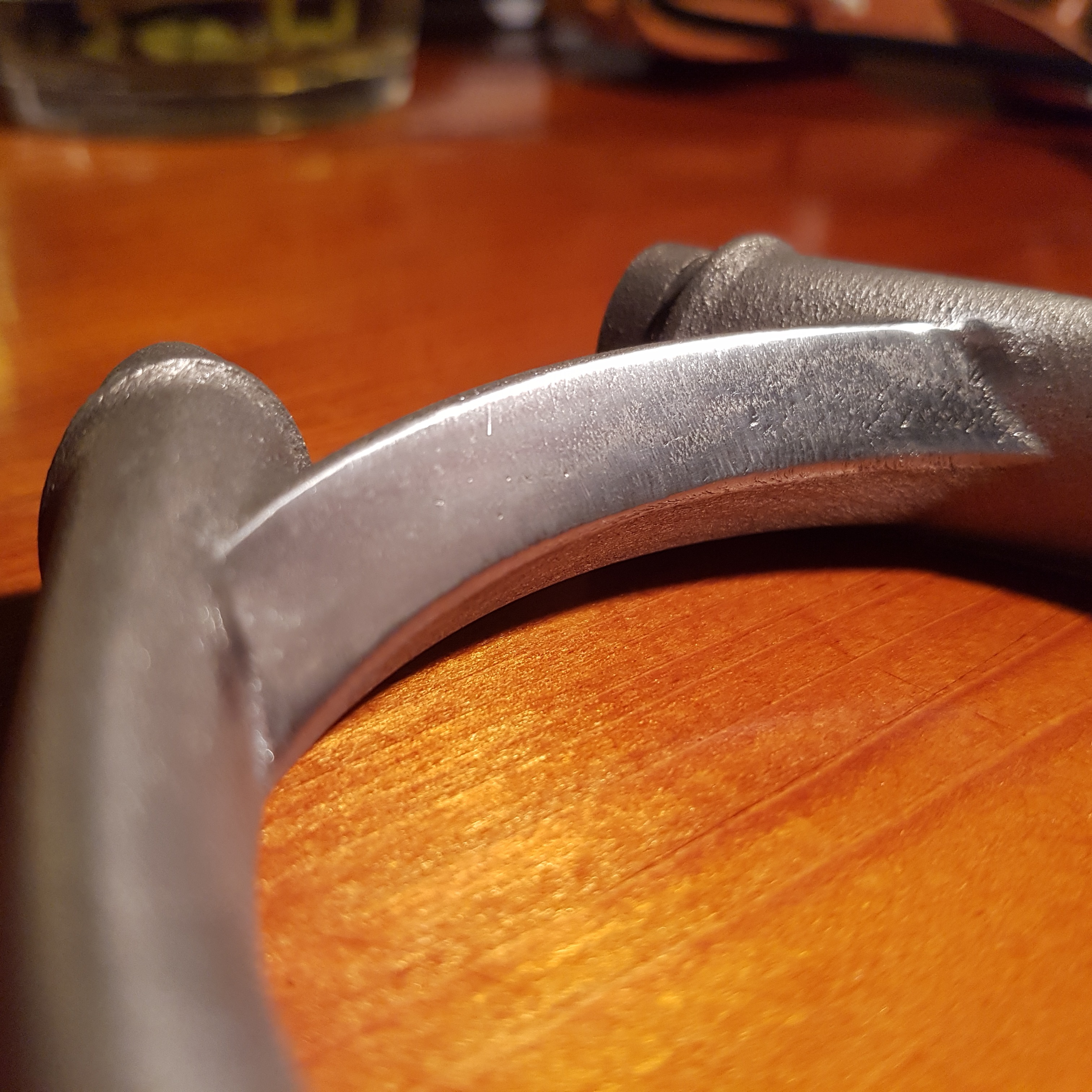
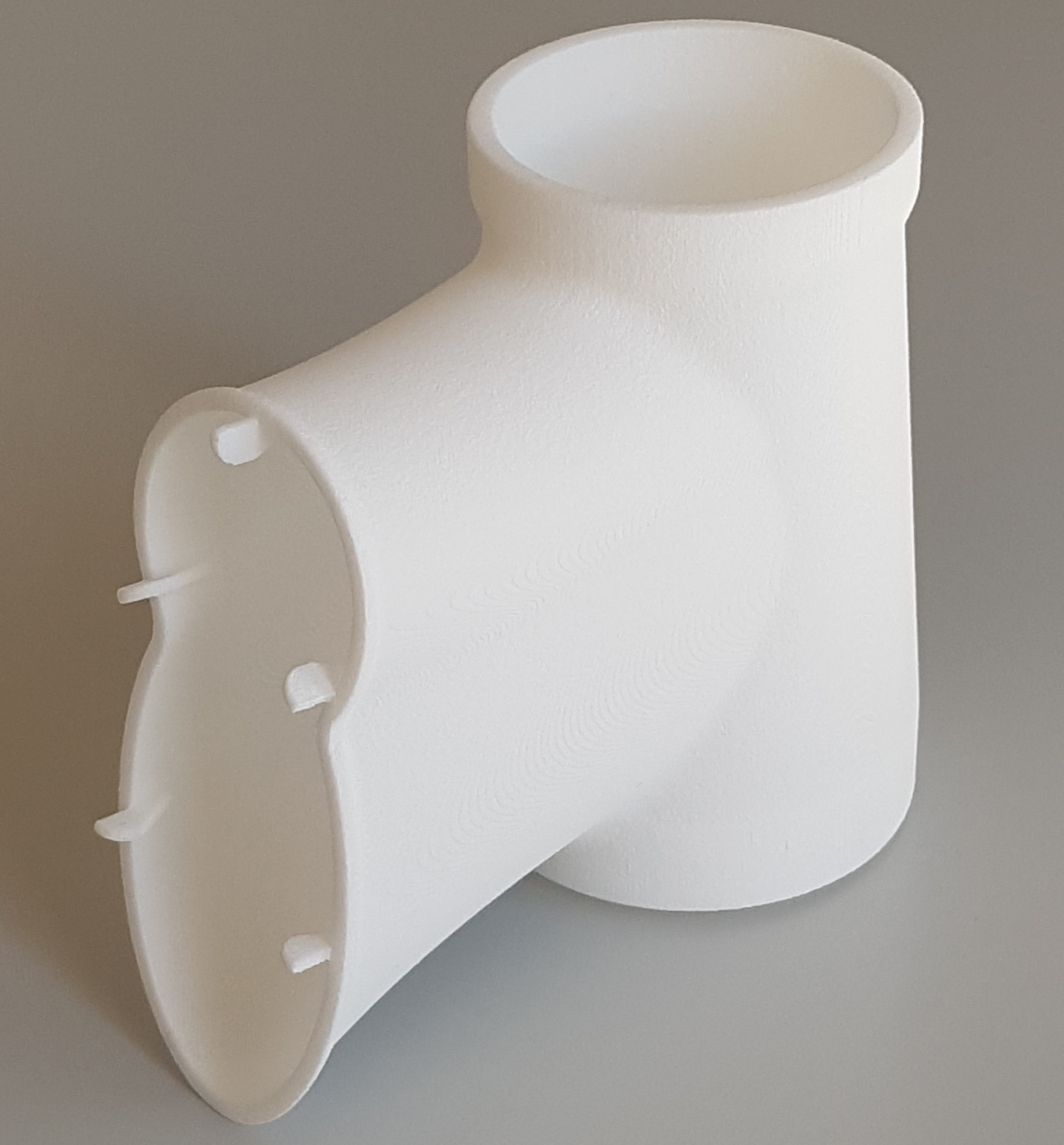
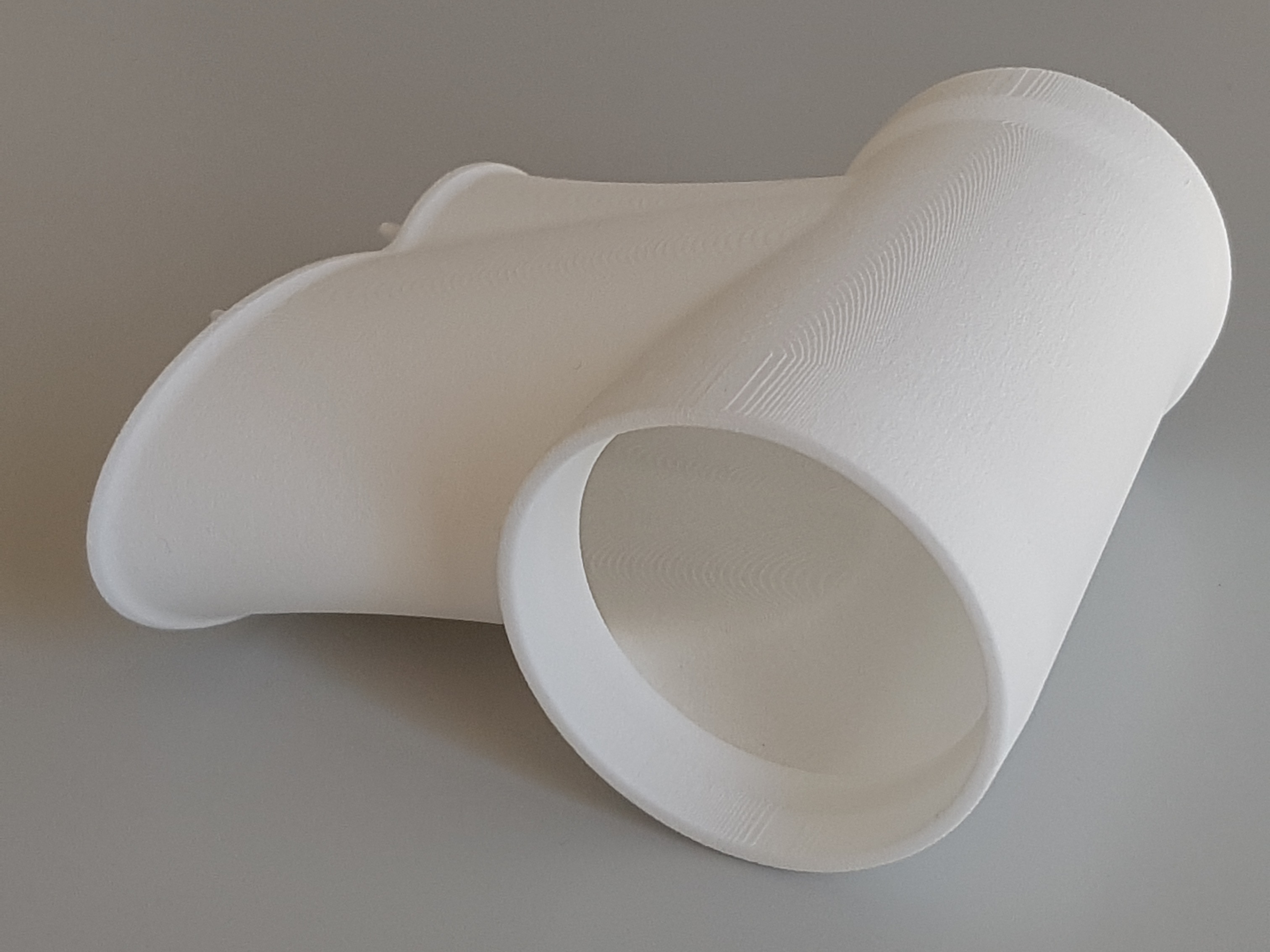
For later welding I included small guiding protrusions to fit the part precisely into the cut-off tubes of the frame. Next to the weld, I added a ridge with less than 2mm² cross section as a material reservoir for welding.
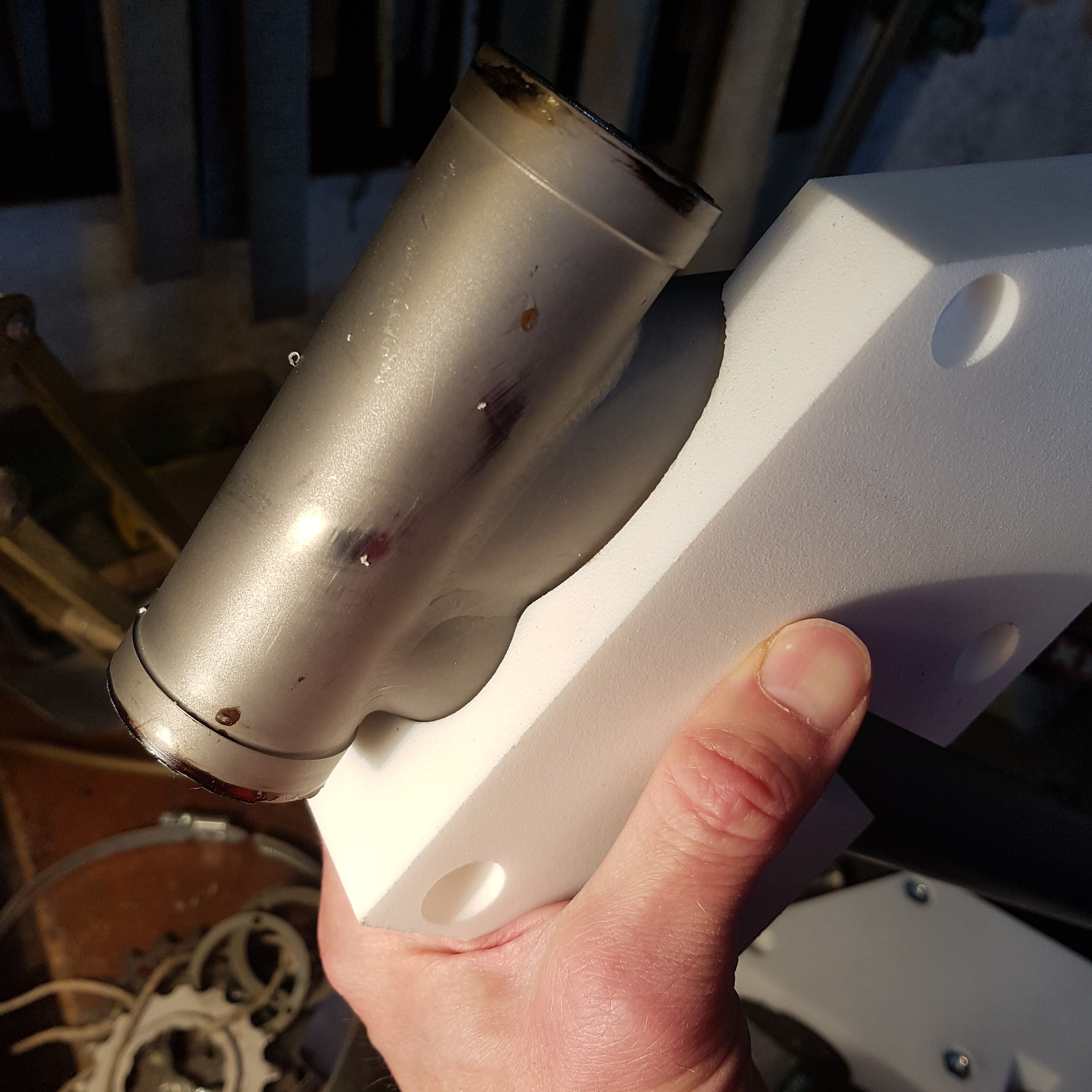
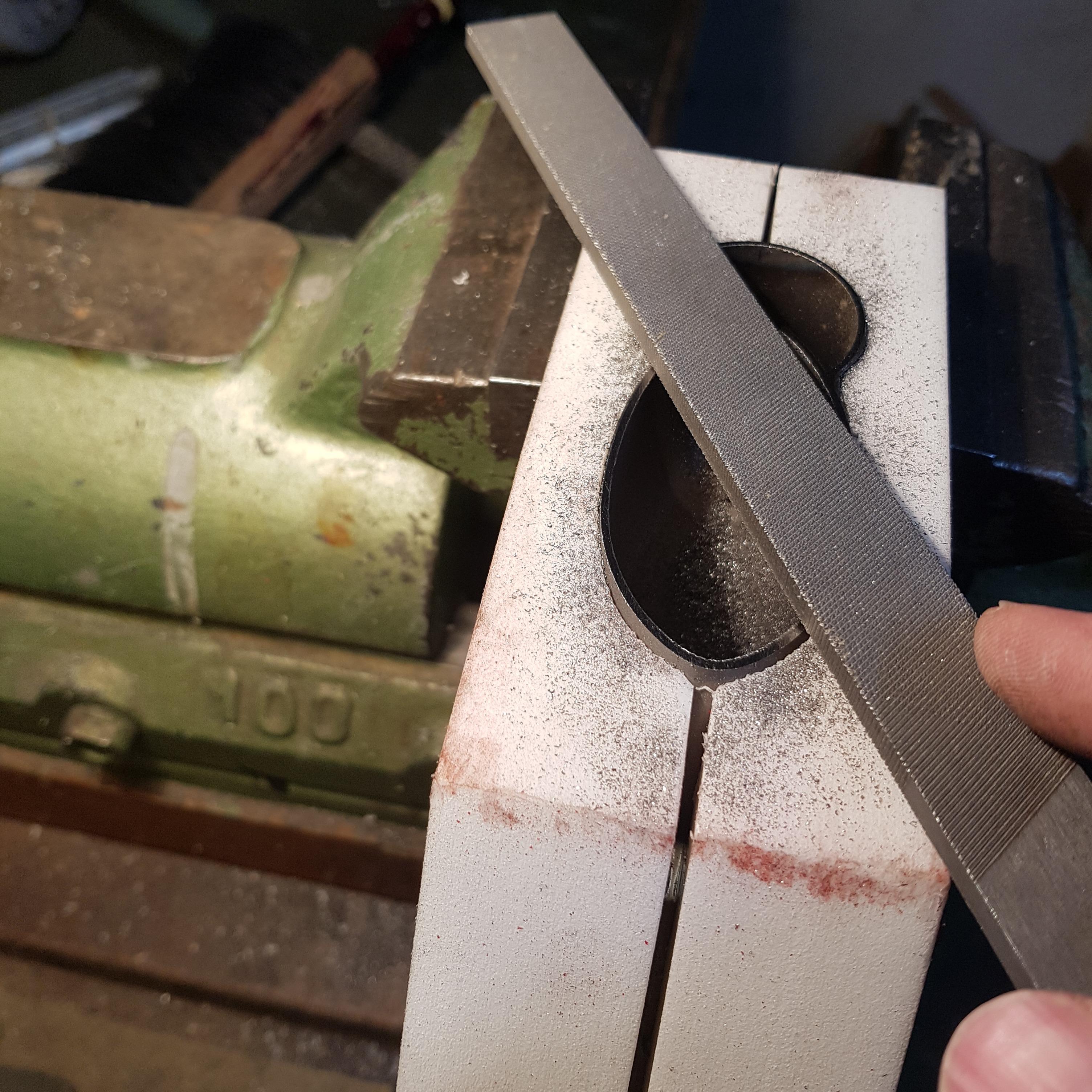
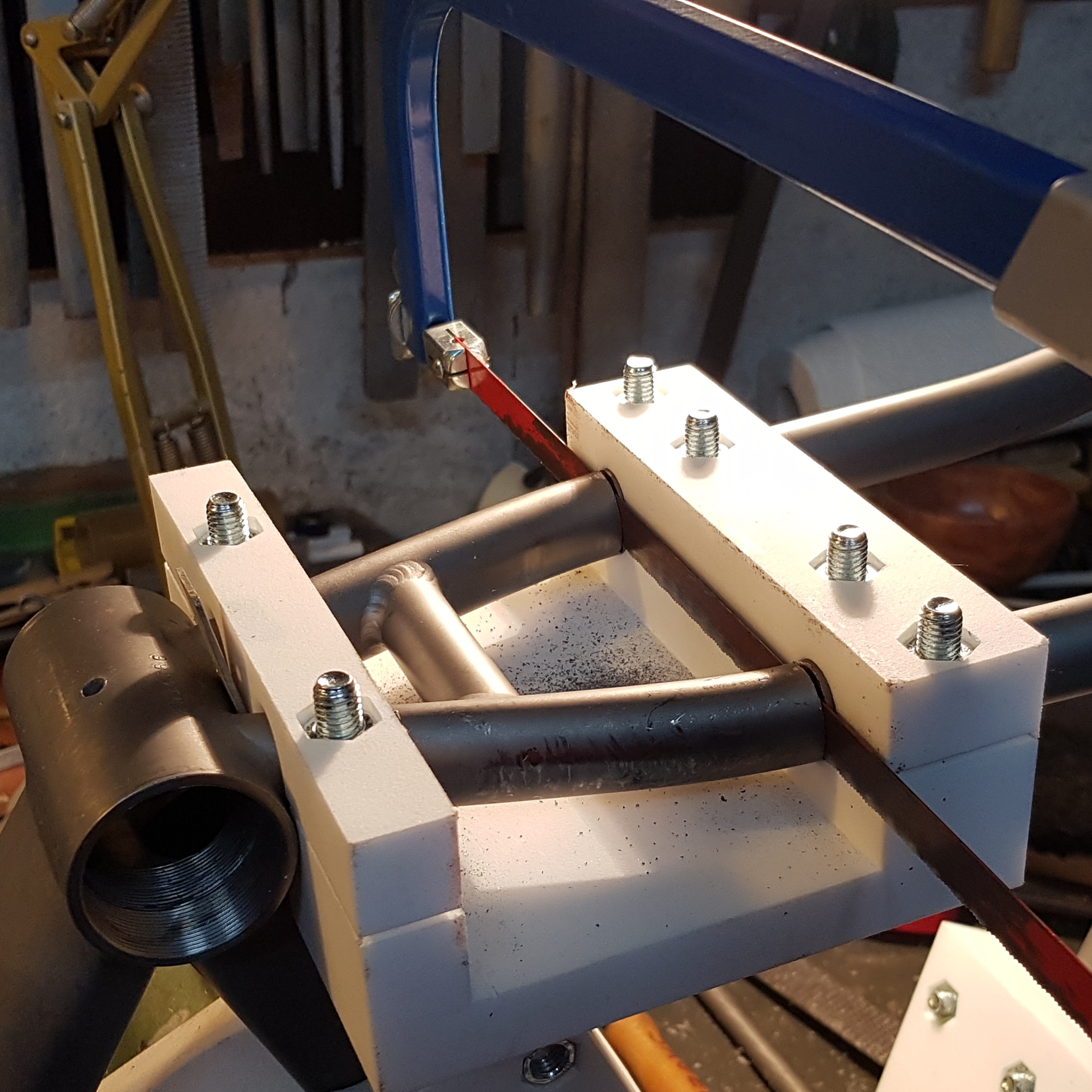
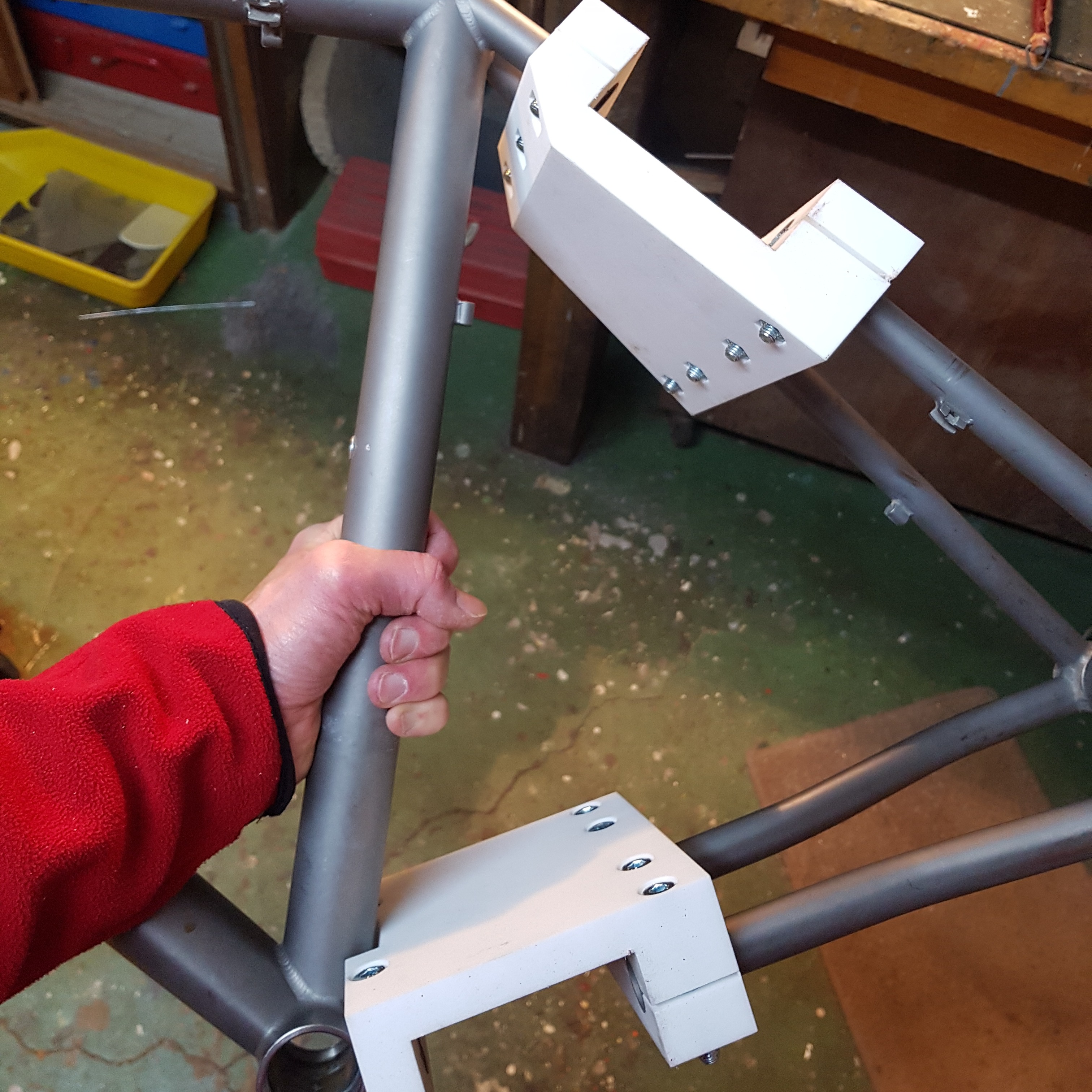
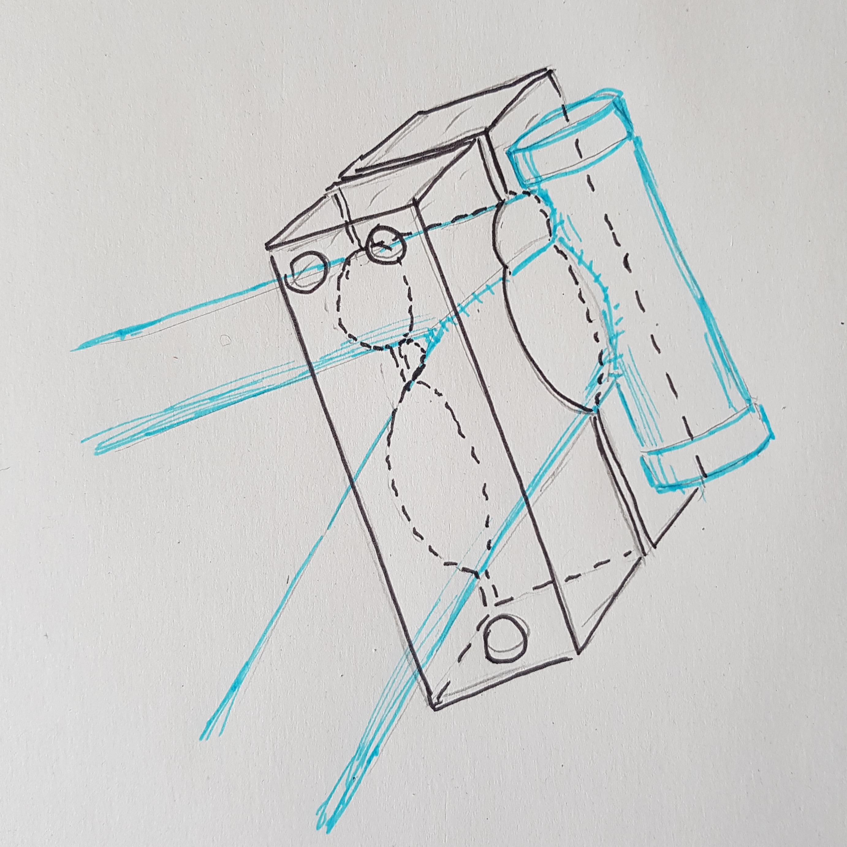
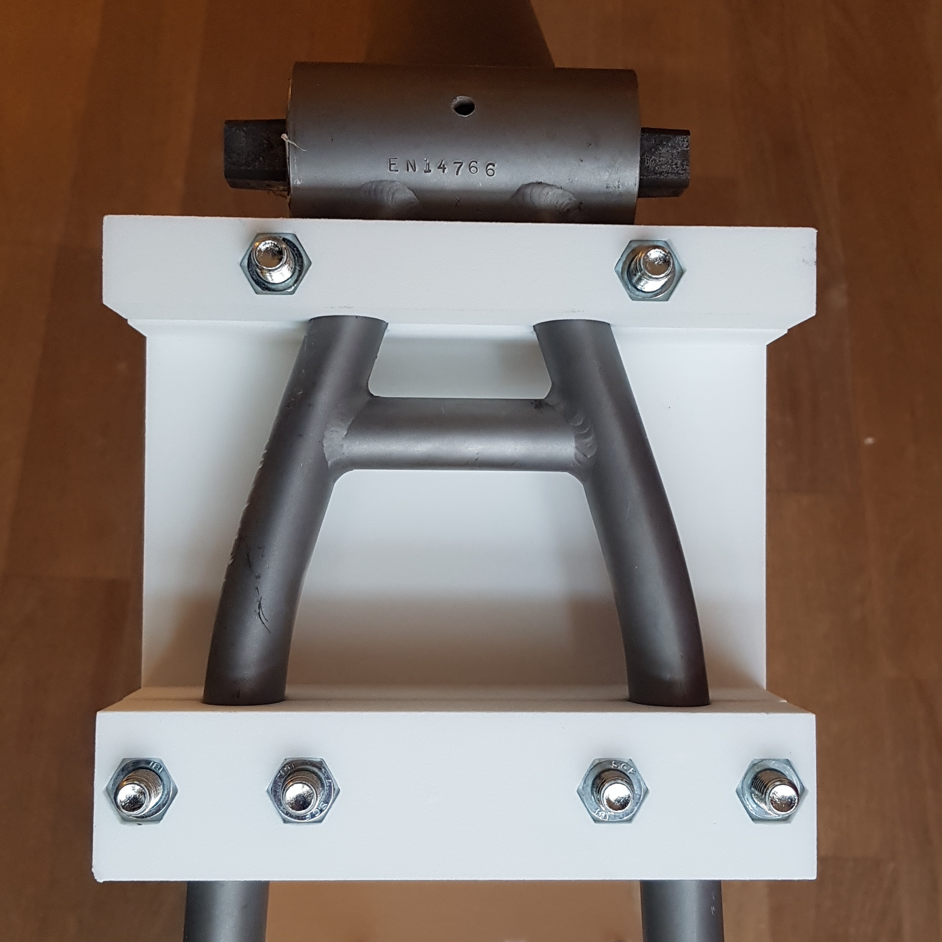
Of course, Daniel would do the welding work in Berlin. But we figured out that I should do all the preparation, i.e. cutting the frame and testing the fit of the resulting titanium puzzle. You may be aware that it is not easy to get a straight hacksaw cut through a thin-walled tube! I realized that I would need a jig, a fixture to help with sawing and filing the cuts. Of course, this could be a 3D printed part as well. In this case, it was a polyamide block to clamp on the tubes. I could saw through the tube and file flush to the surface of the jig, which should provide the required precision.
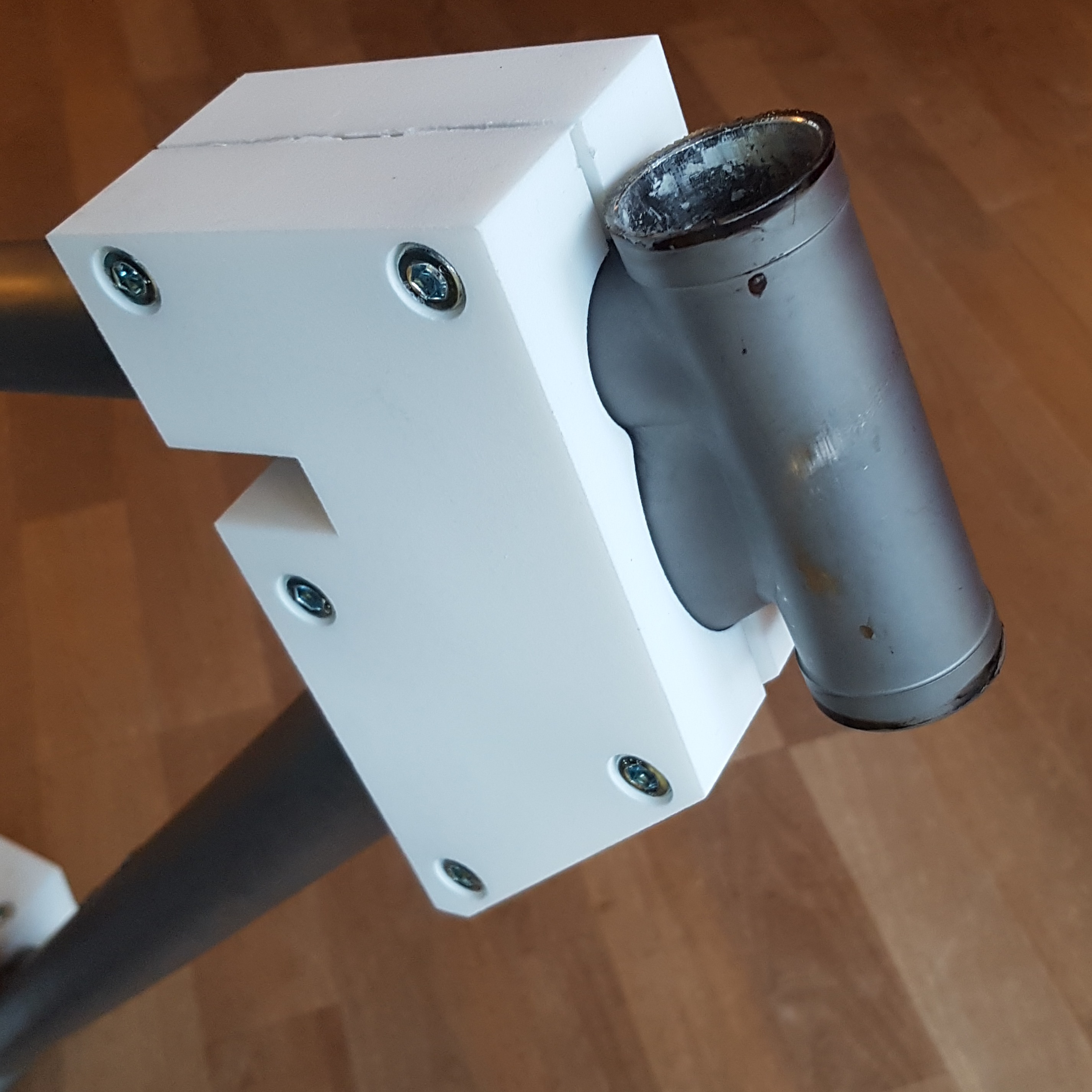
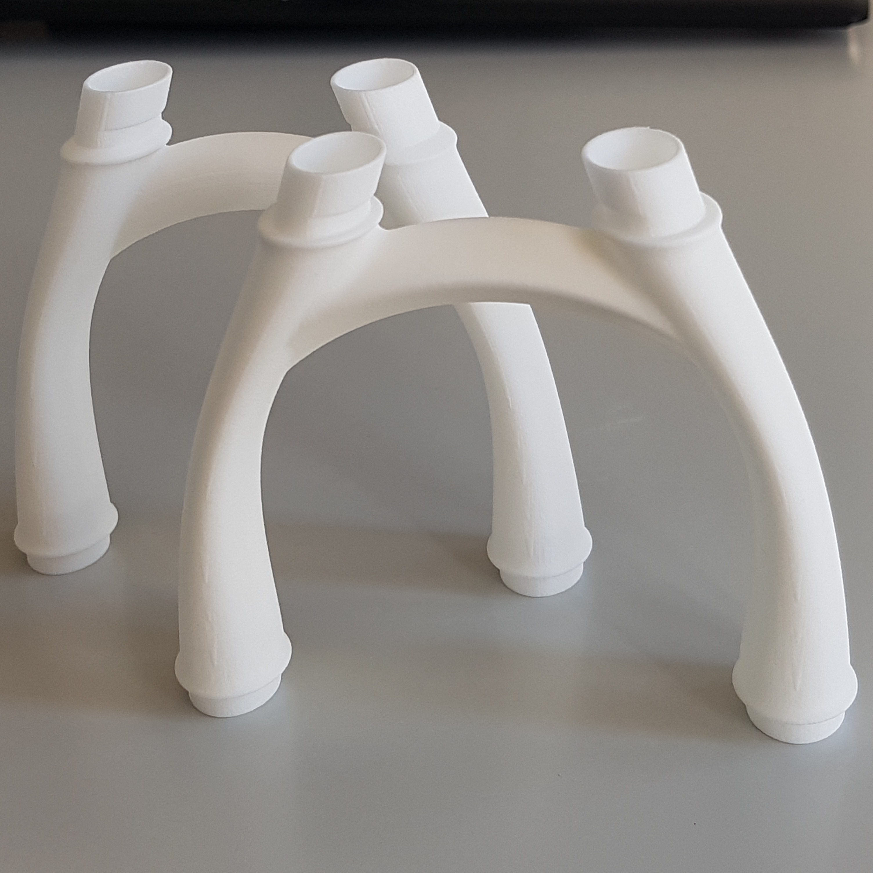
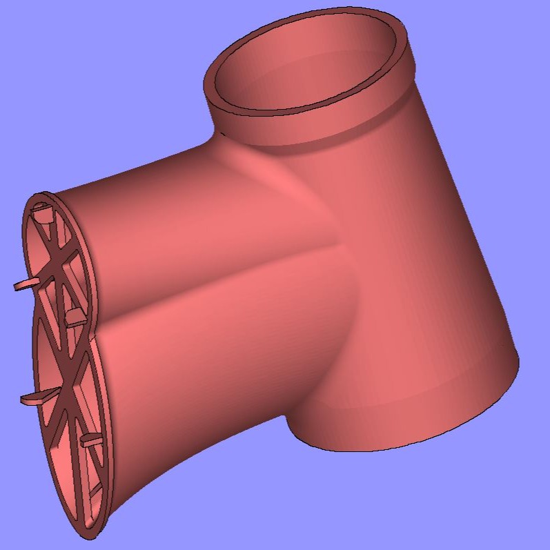
Speaking of polyamide 3D prints - I was very quick to get my headtube CAD file printed as a prototype. Besides the satisfying feeling to have my design in physical form, the part gave me a good impression of its stiffness and weak areas. I reinforced the bearing housings as they felt too floppy. The initial design had no reinforcement at the back opening, which was too weak as well. I went through a few iterations until the part felt solid and the metal printing experts approved it.
All the prints have been done at EOS where I was employed. Time to give a huge shoutout to my coworkers there and everybody involved with their time and their expertise - you are just great.
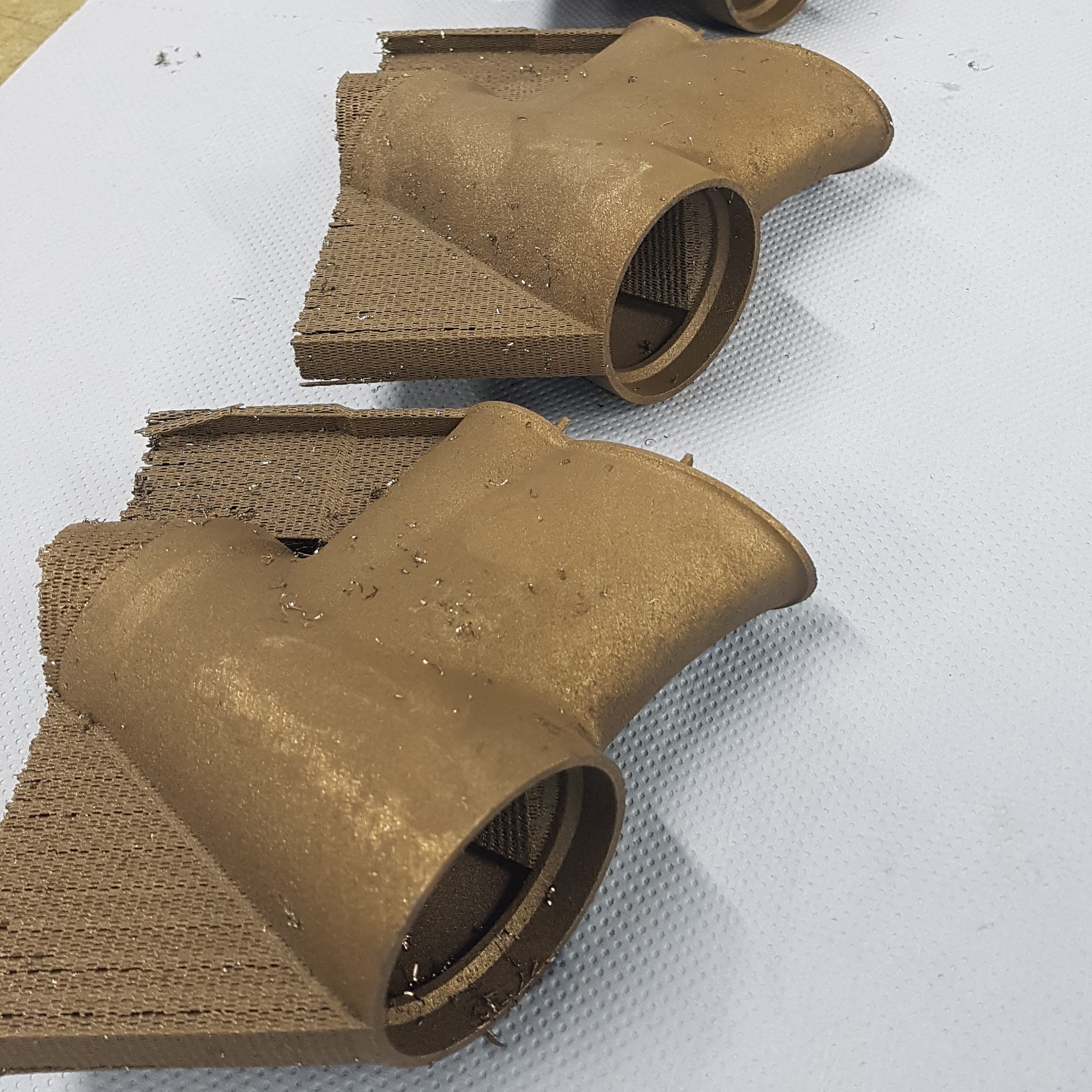
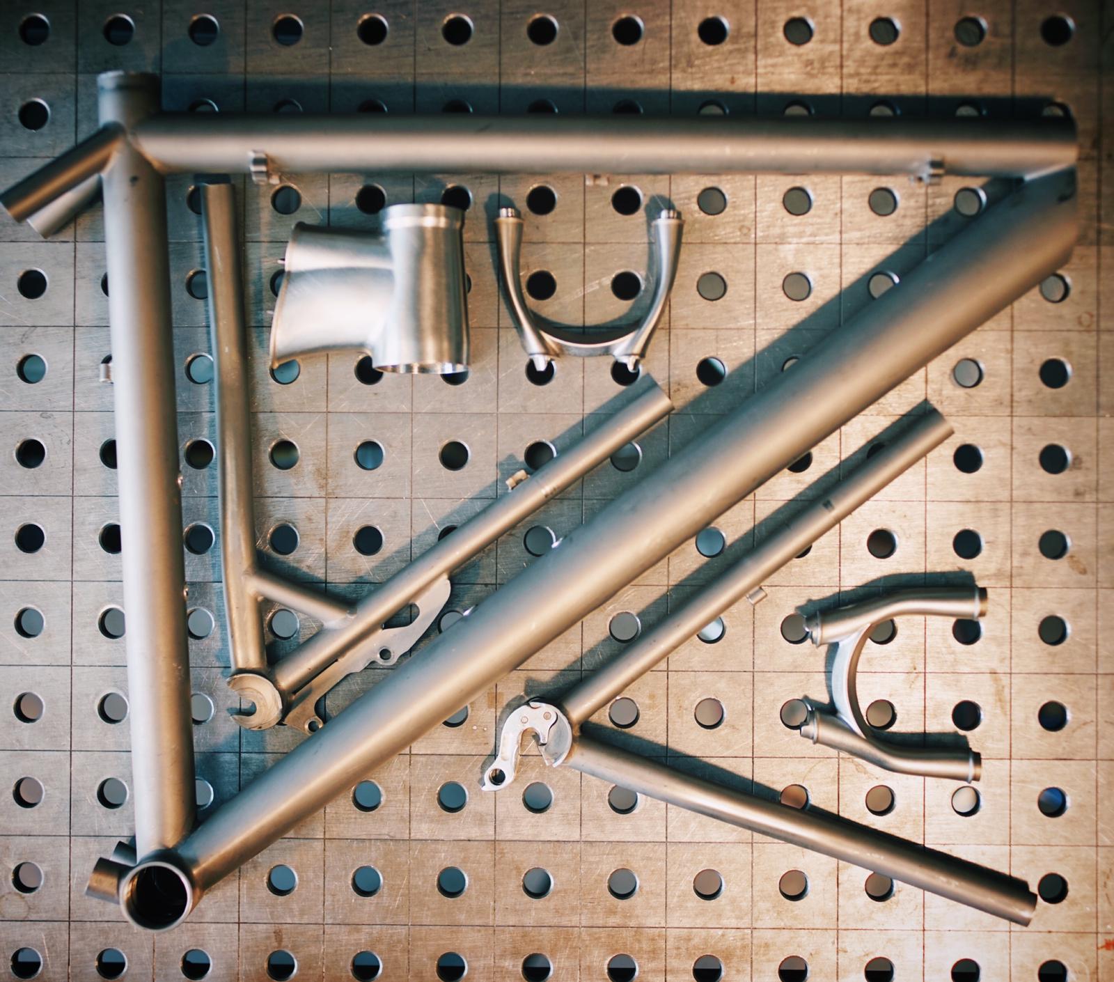
The plan was to set up one metal print job for all the parts. So I had to finish the design of the chainstay and seatstay inserts first, then we would go to data preparation, support generation and job setup for the actual titanium build.
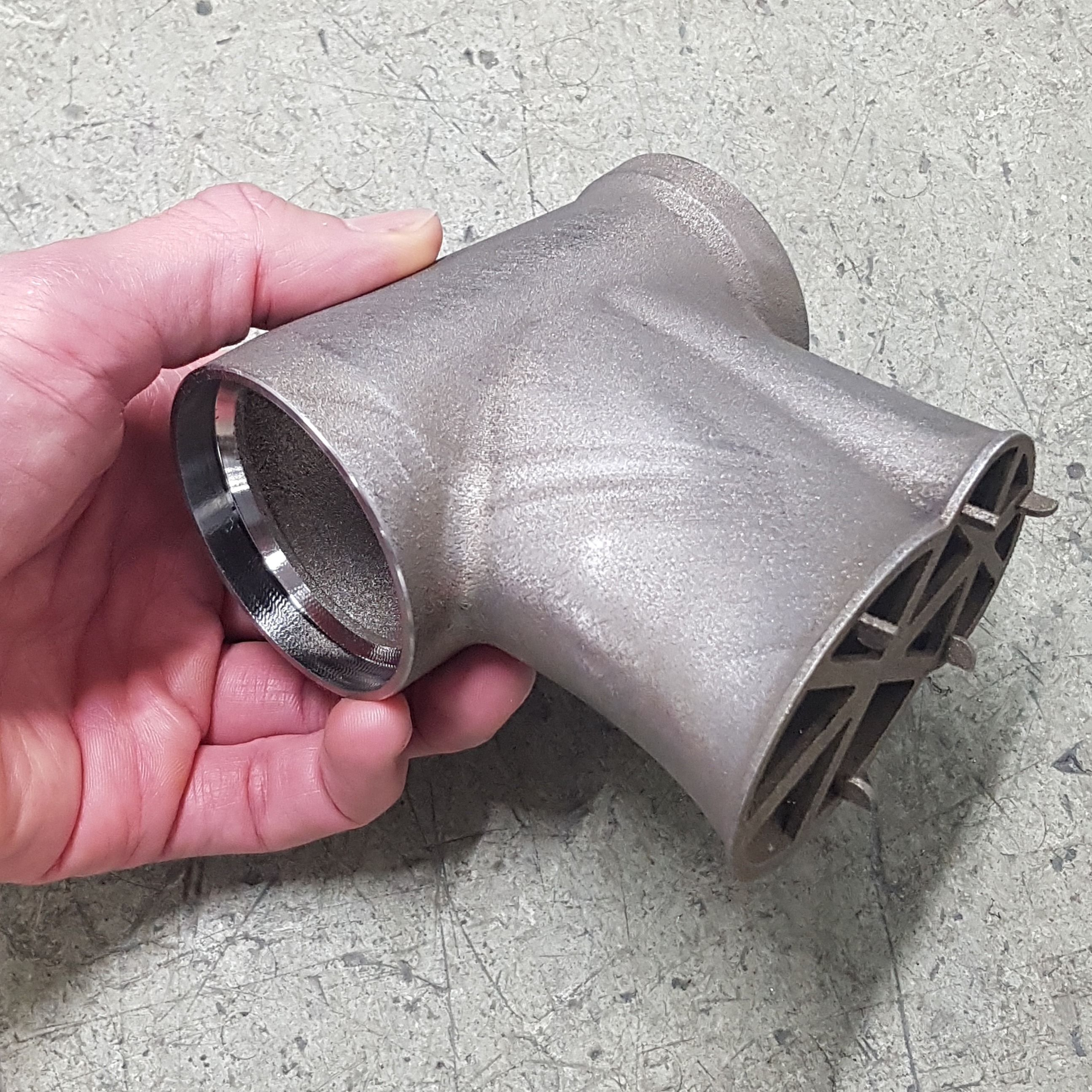
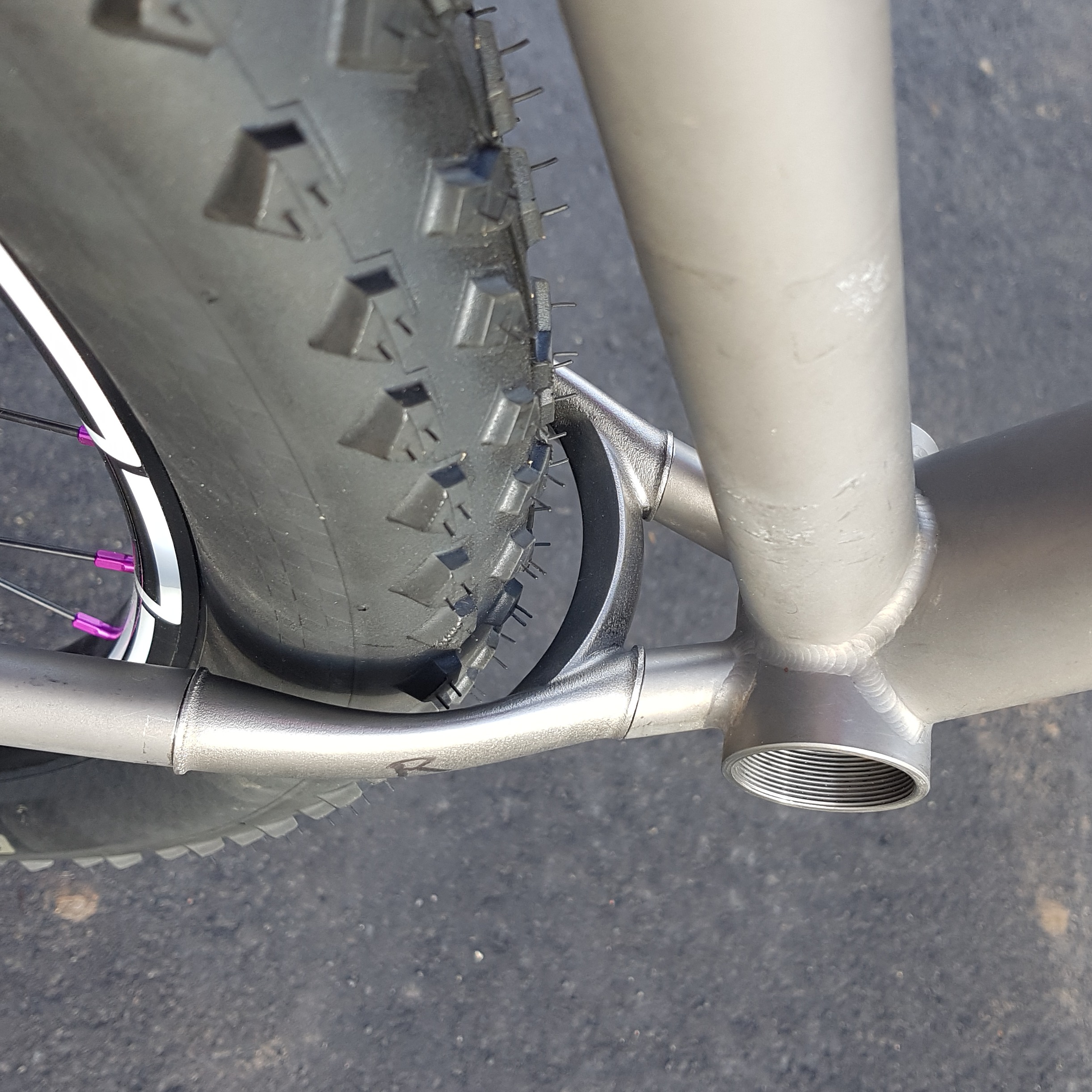
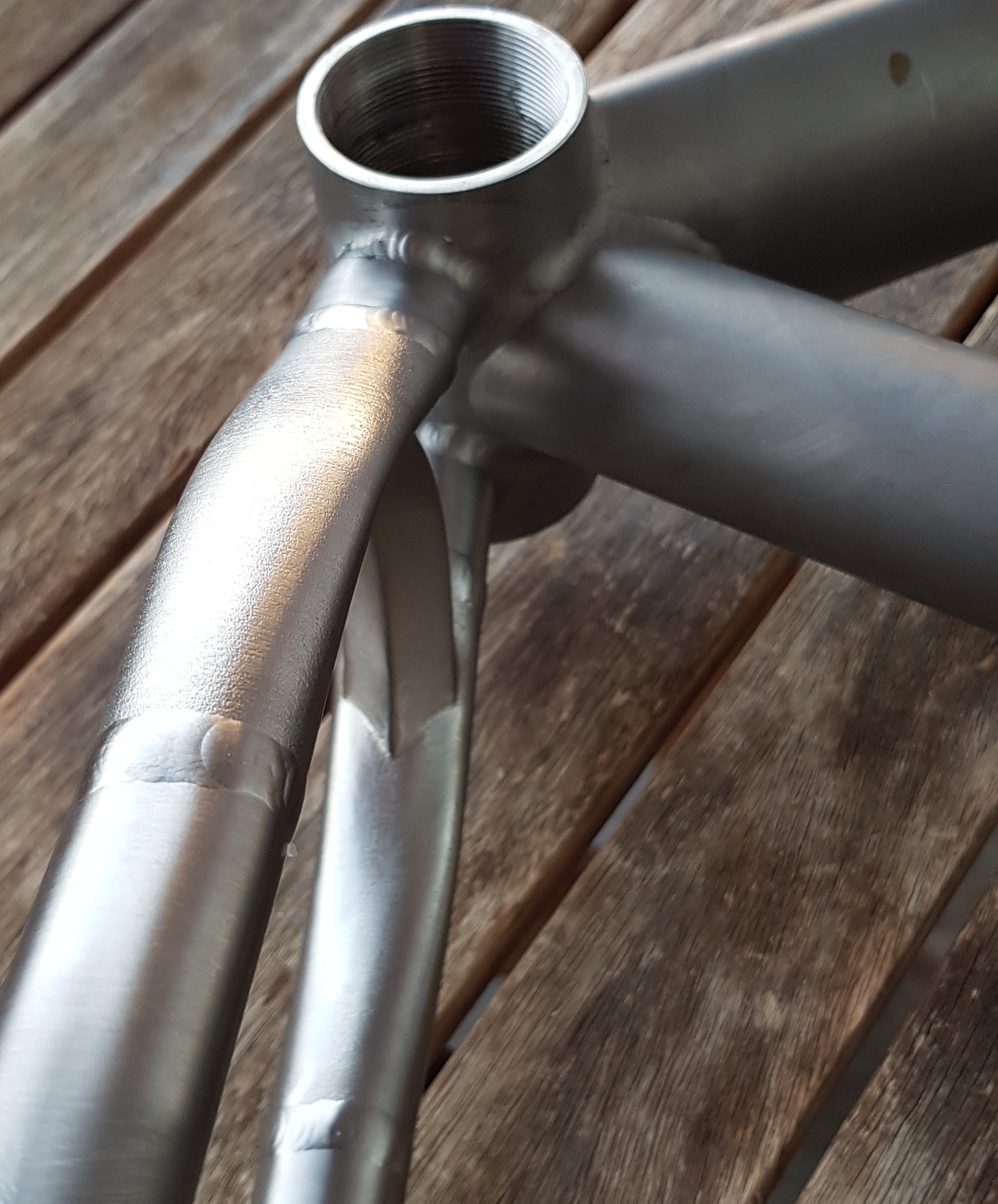
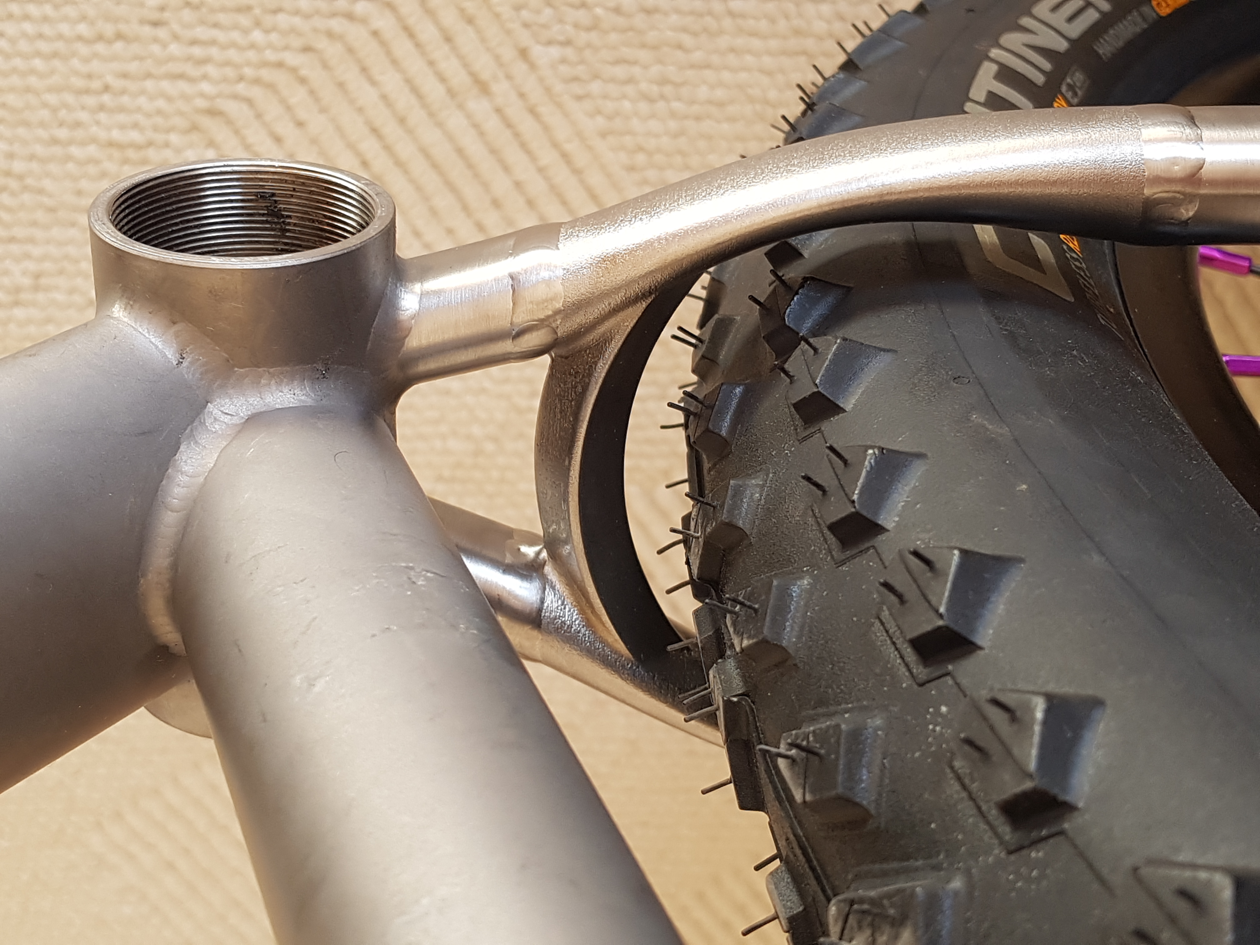
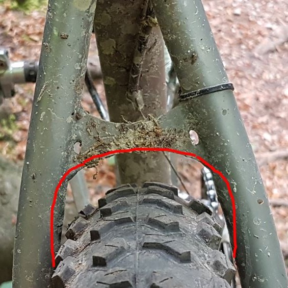
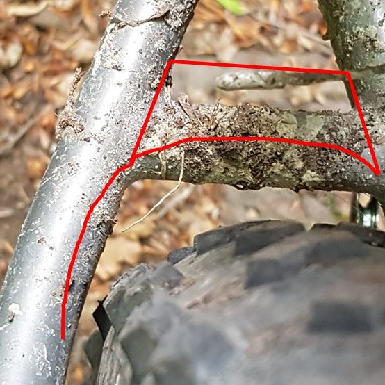
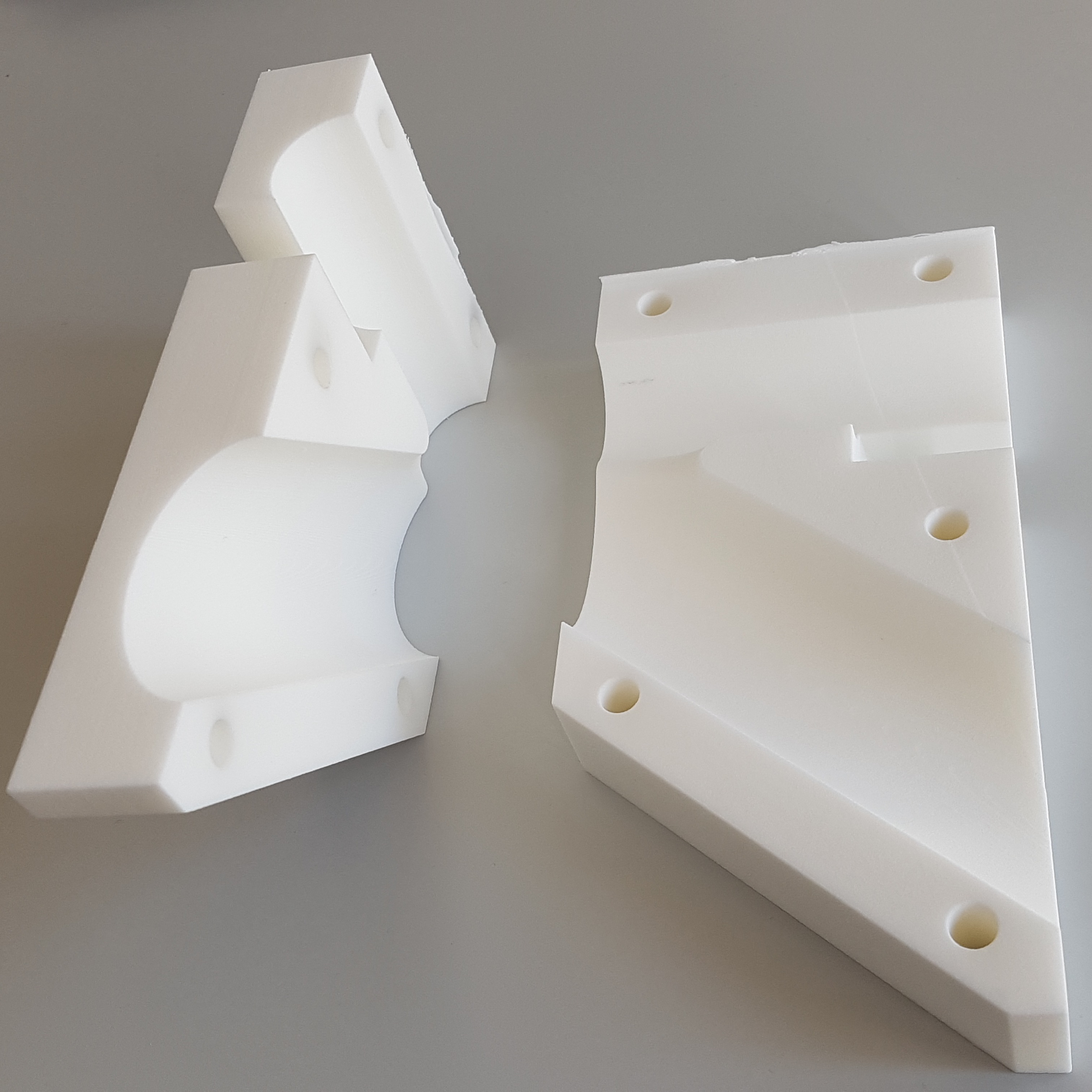
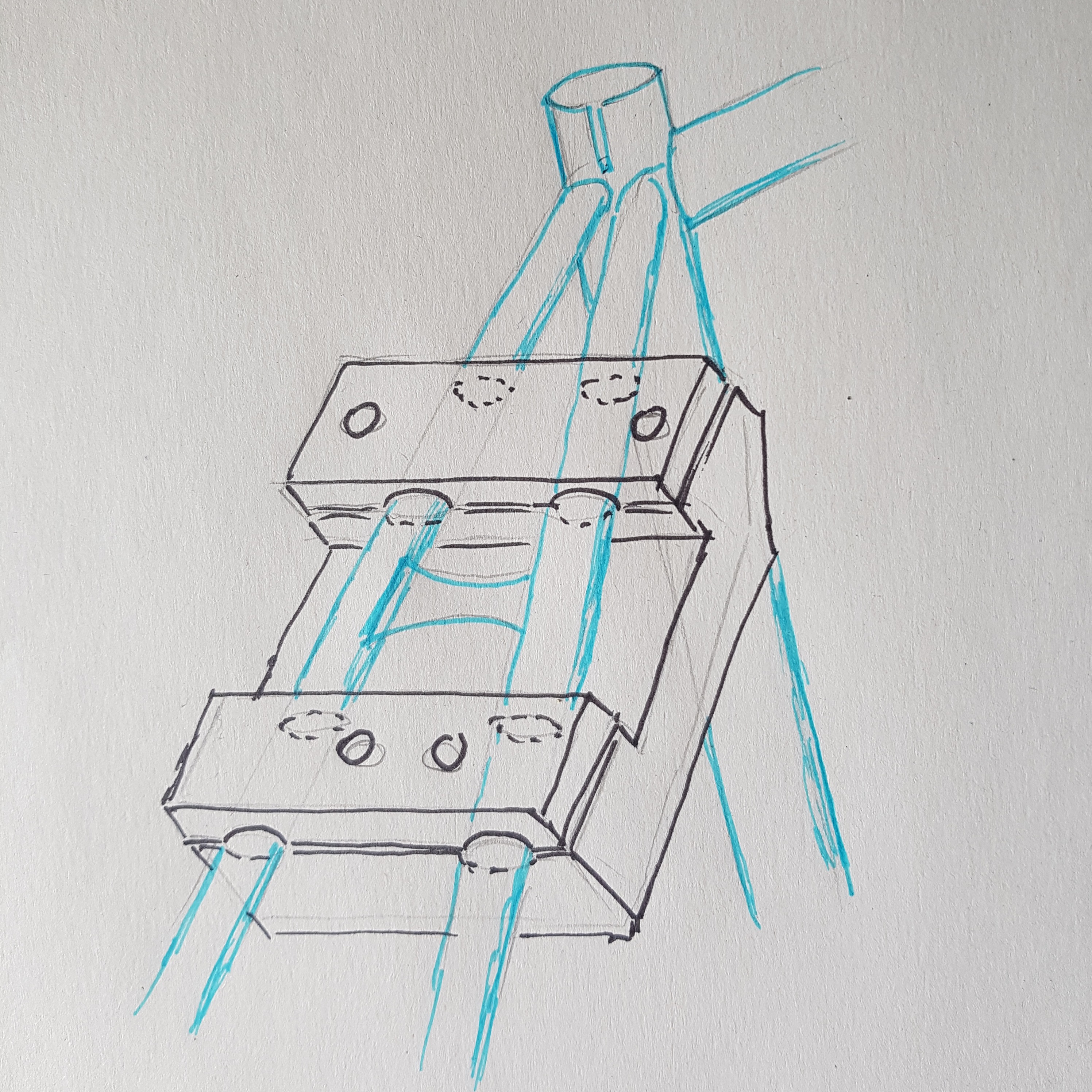
Off I went for the next design sessions. Similar procedure - decide for the position of the surgical cuts, measure all relevant dimensions at the section, and start modelling in 3D CAD. Tire clearance was defined around a 27.5x2.6 tire, which I assumed to be 66mm wide with a 355mm radius. For a 4mm clearance I had to provide 74mm free space inside. The chainstay insert kept the original outer silhouette for unchanged chainring and crank clearance. The new tubes got a slim elliptical cross section with a reinforcing horizontal wall inside.
For the seatstays I added an outward bulge to widen the space. While at it, I included fixtures for cables and bosses for a rack.
Both parts were planned to be built standing upright. With that in mind, I played around with various designs for the connecting struts until I had something both pleasing and printable with a little amount of support structures. Again, plastic prints helped me to pick the nicest version.
Cube must go: Insert design and prototyping
The jigs for cutting the frame were designed in the same 3D model. Again, they used the principle of clamping on the tubes and providing a flat surface at the planned cut to guide sawing and filing. As I did not spend too much time on an elegant design, they came out clunky and heavy. But they provided peace of mind for the upcoming surgery.
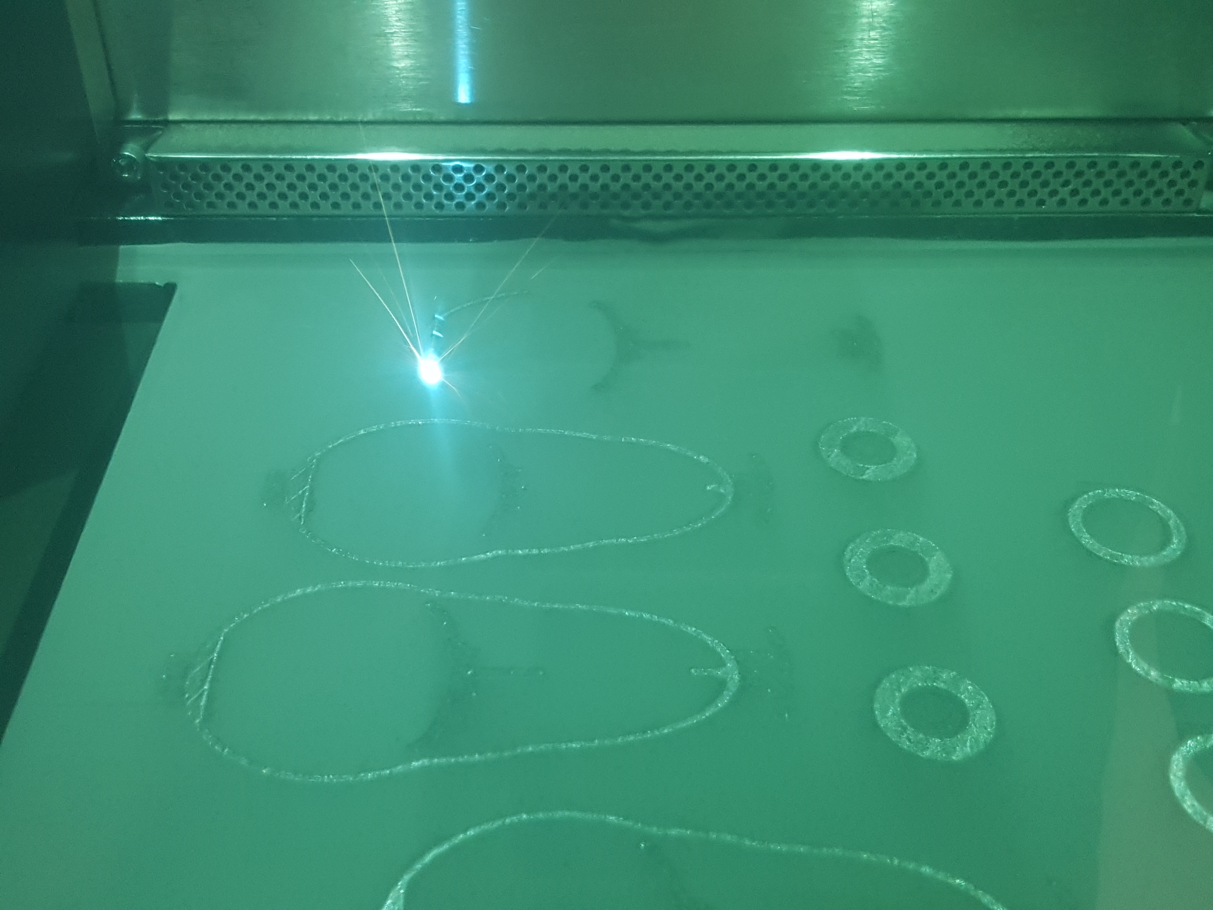
You ask, when does this guy hit the print button for the actual parts, finally? In fact, I had to be patient and confident myself for a long time. Industrial 3D printing is advanced manufacturing technology. I took a while until there was a slot available on one of the printers. Peter and Vicenzo, both senior application specialists, worked with me on the project in preparation of the build. Parts were arranged, support structures generated. The printing process - Direct Metal Laser Sintering (DMLS) - is a layer-based generative method that uses pure metal powder. In each layer, the cross section of the parts is molten by a laser beam. It solidifies rapidly, and the parts grow layer by layer. "Titanium is a bitch", as Vicenzo mentioned: the material had been proven to behave sometimes unexpectedly. We dealt with internal stress, warpage and deformations and went through a few loops, optimizing both part design and support structures.
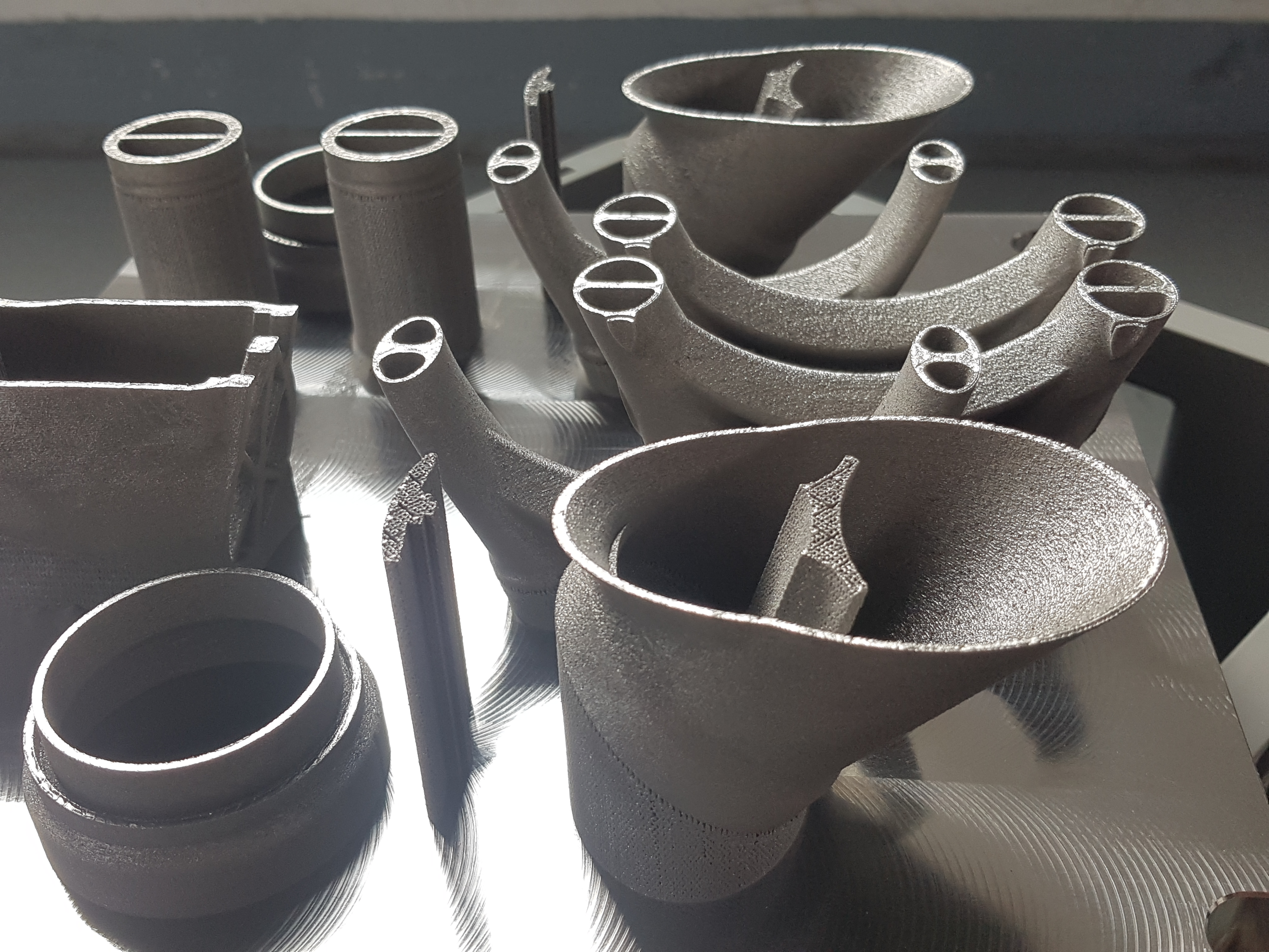
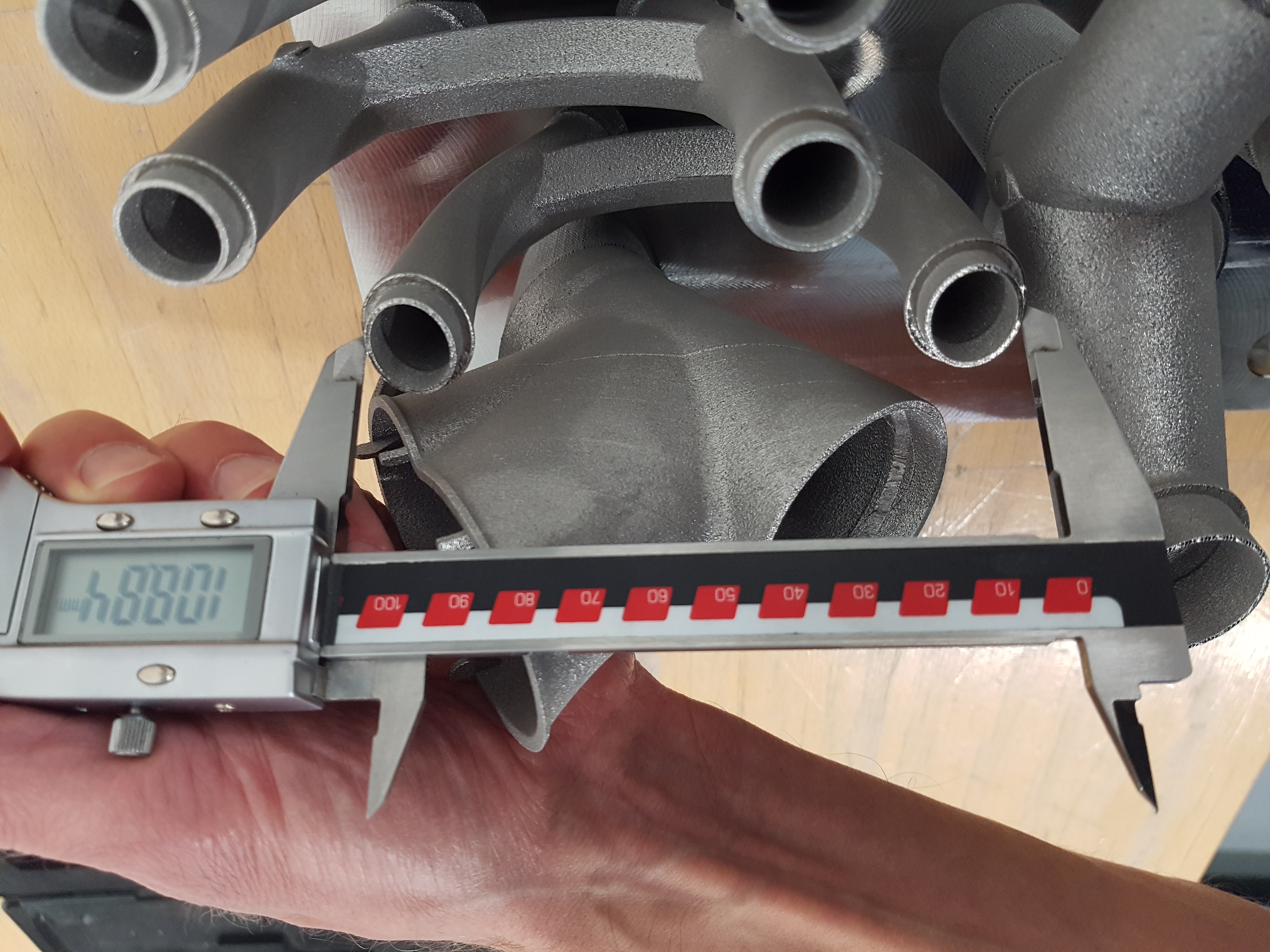
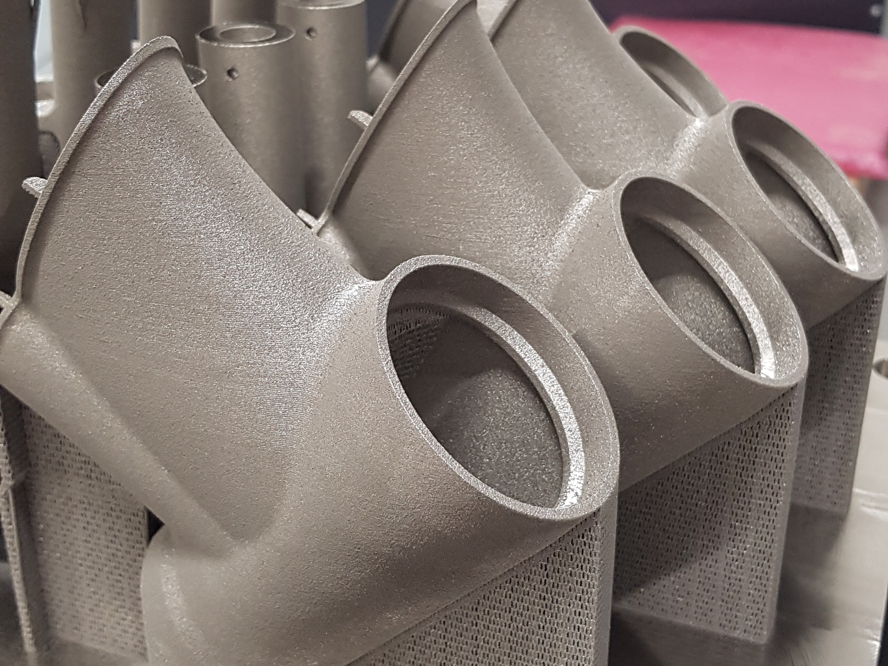
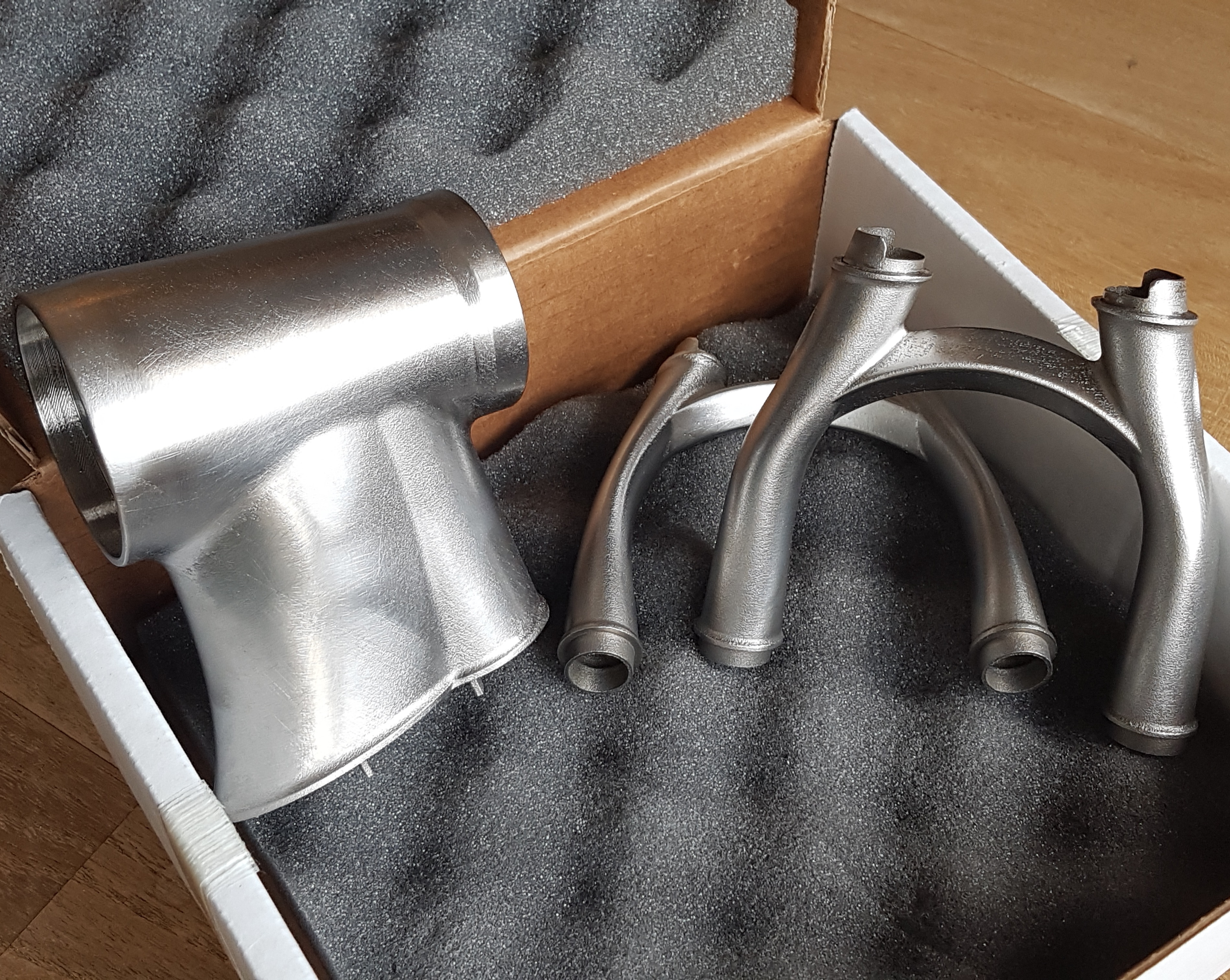
What a great feeling to have the parts at hand - but in real life, they were still bonded on the build platform. They got heat treatment to release the internal stress, then a whole chain of post-processing started, which involved real, dirty work. Sawing off the platform, support removal, machining bearing seats on the lathe, drilling threaded holes, surface finishing. I was back to craftsmanship, the parts started shining, lighting up the bleak time end of 2020.
Support removal, machining bearing seats, surface finish
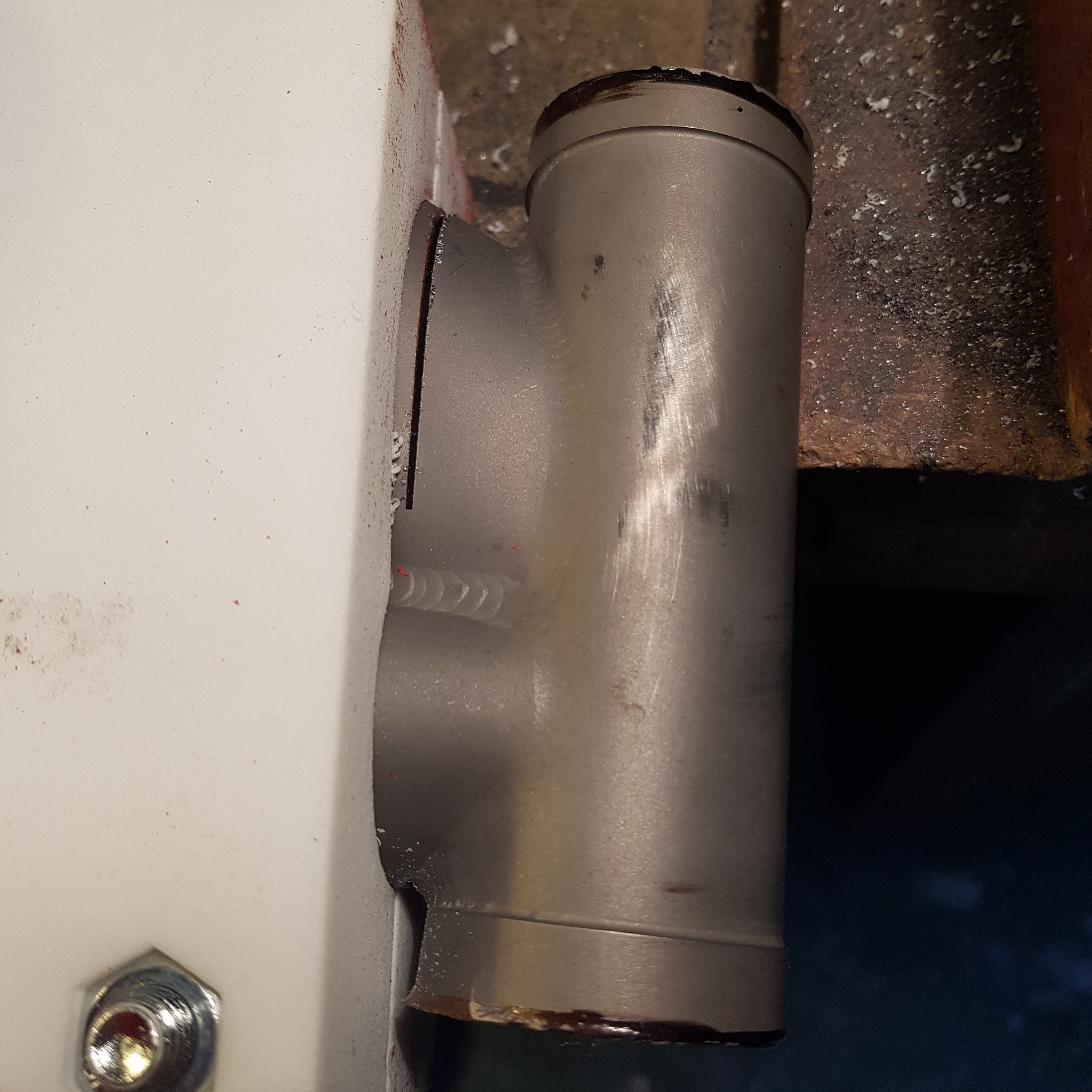
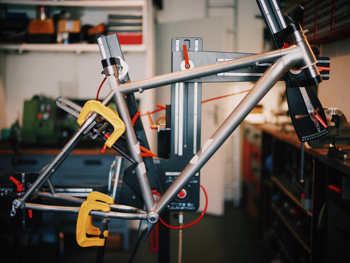
Now nothing stood in the way to prepare the frame. Bike parts went into a plastic box, and I retreated to the workshop, with the frame, the new parts ... and the jigs. This was the point of no return, and I can confirm that it is emotional to saw one's own bike frame to pieces. The operation went well, and the printed parts needed only a few finishing touches to fit neatly into the tubes. Already now the looks were great, and the new back wheel with the big tire had very reasonable clearance.
A few intense hours spent in the workshop
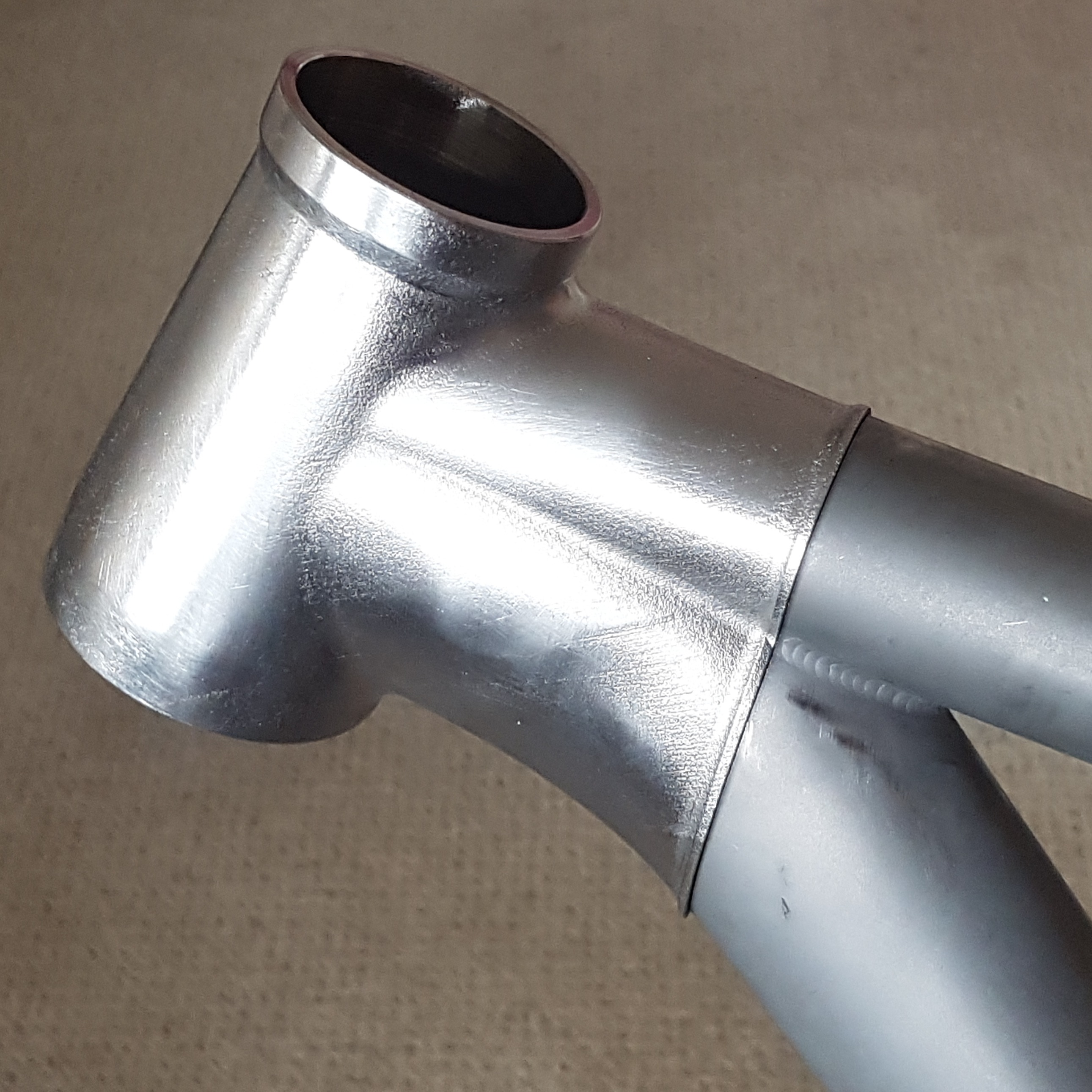
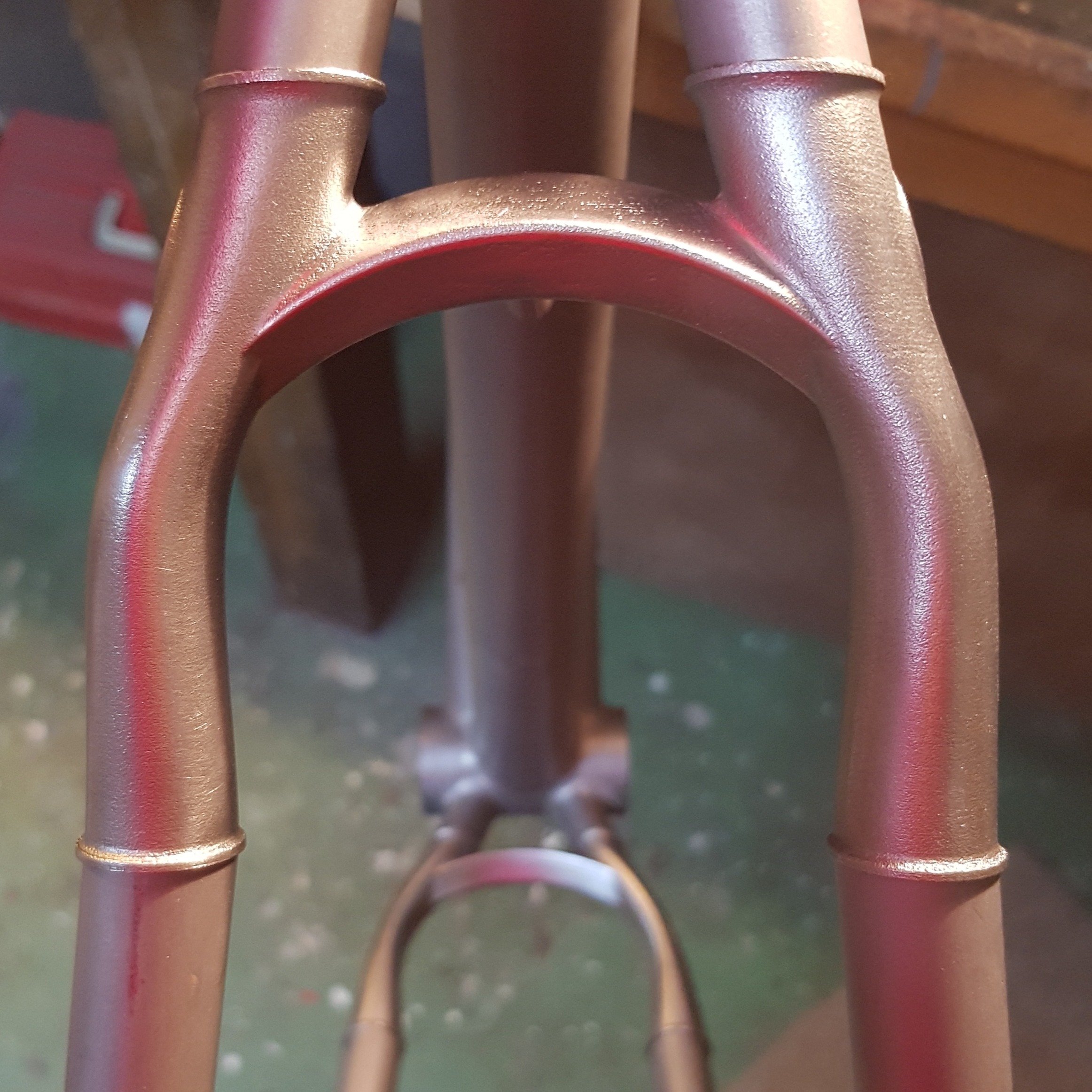
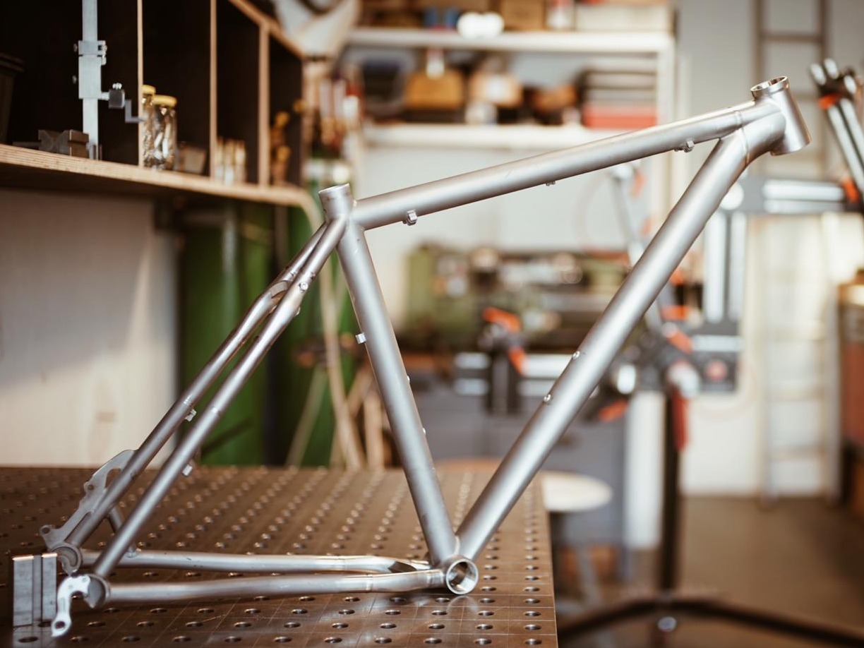
The whole set of frame parts got packed neatly and was sent to Daniel in Berlin. He did his welding magic in February 2021 and shared pictures and experiences. He could mostly confirm my geometry measurements in his frame jig, and the welding worked out fine, even if my material reservoirs turned out to be excessive. He noted remarkable stiffness and strength of the rear end while straightening the frame after welding. Needless to say that the frame got a spotless finish and looked beautiful already on the pictures he sent me. Very well done!
From the puzzle to the frame - photos by Wheeldan
Frame and bike weight were not a top priority, but I weighed the frame before and after the conversion. The weight increased moderately from 1444g to 1562g, still light for a capable titanium hardtail frame.
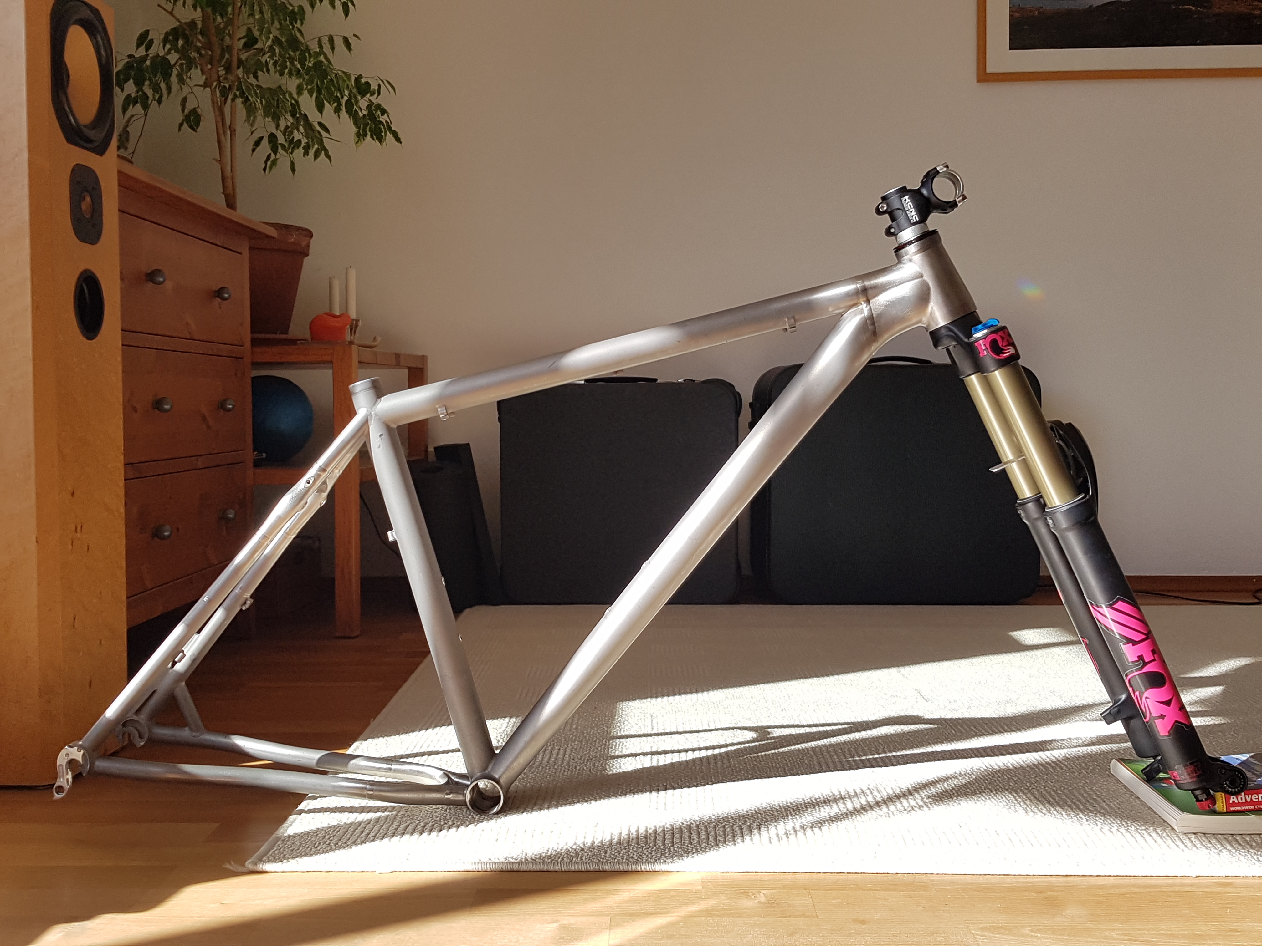
The living room turned into a bike workshop for one afternoon for assembly. The bike emerged as a beauty, and I felt like being a small kid at Christmas again.
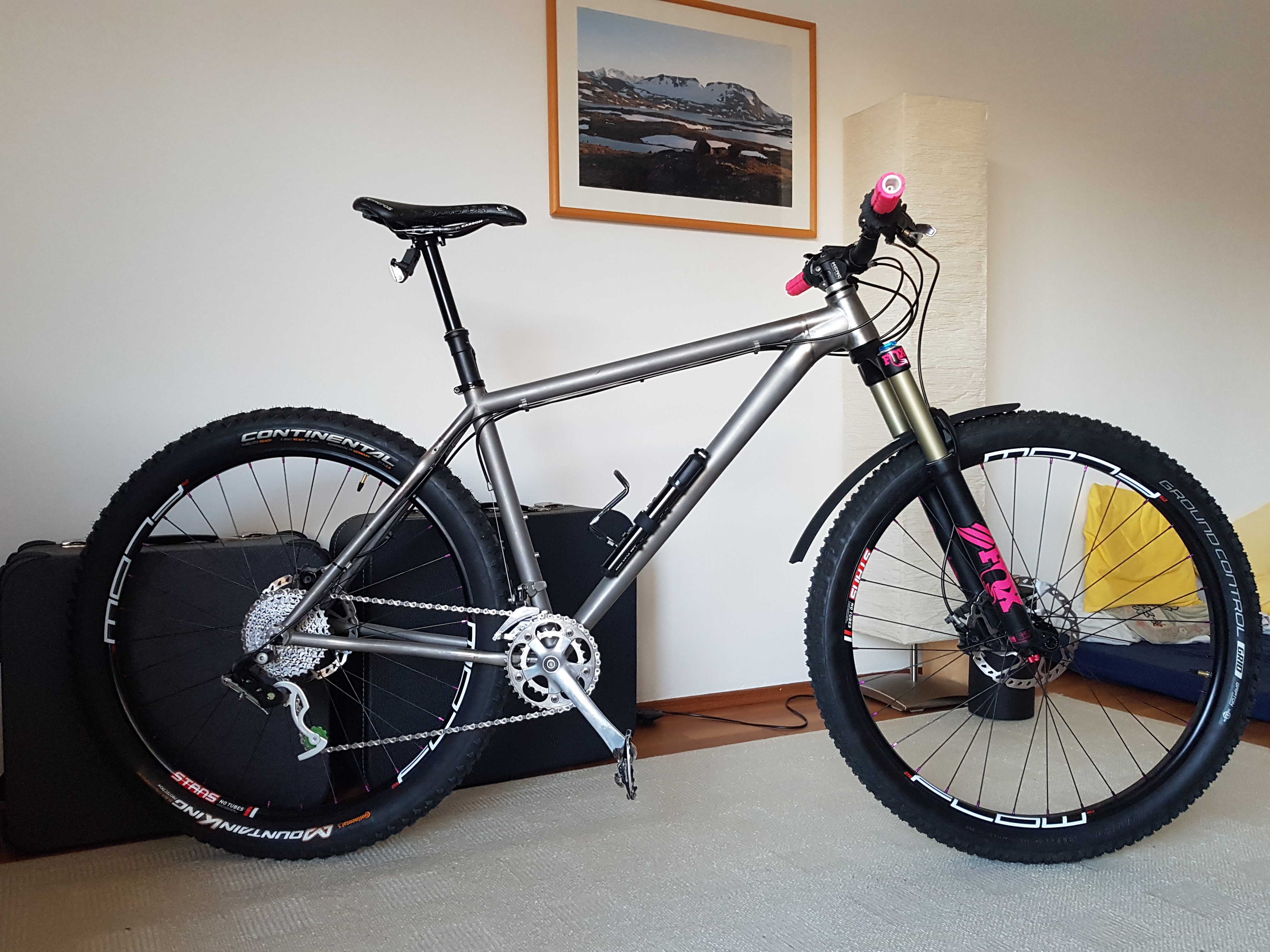
I headed out for a first test ride the same evening. Childhood memories again - the feeling that you have got your new bike after you have outgrown the former one. The home trails with roots, pebbles, little climbs and jumps had turned much smoother, softer, easier. Geometry, body position, steering, all felt very well balanced, the bike gave me an instant "let's try this" nudge at the typical trail features, while covering ground without being sluggish. The wheelbase had grown more than 8cm, completely in the front center length. Tight corners had to be taken differently, and steep descends were so much more relaxed. I never experienced wobble or a lack of stiffness, rather reassuring stability at any speed.
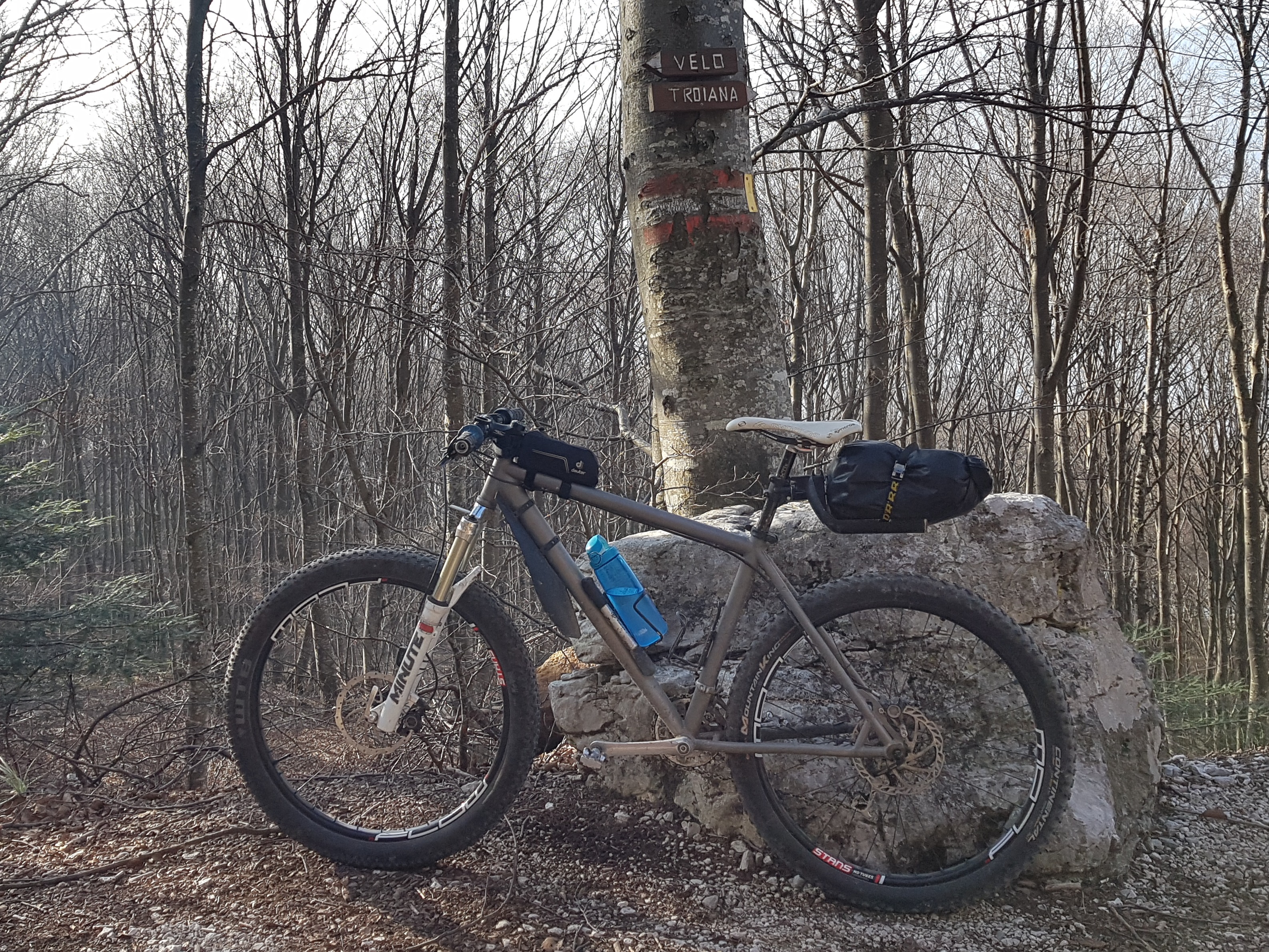
I write this down five years after the first ride, still this is my all-time favorite bike. It has seen some evolution, I soon moved from my old 2x8 drivetrain to 1x11 (I know, late to the party, again!), swapped the handlebar for a slightly wider one with some upsweep, tried various tire combinations, replaced the harsh fork damper with a better one, exchanged brakes, fitted a longer dropper post, moved from clipless (click) pedals to flats - yet, the core character stayed the same. It is my go-to rig for the demanding trails around Tromsø, well suited for steep, narrow, technical stuff. Luckily Witslingers made me a custom frame bag which provides an even more distinctive look. You can see the bike maybe a bit too often on my Trail Therapy website - the simple reason: I like this thing. And it connects me to lucky moments, over and again.
Finally, a few learnings - what would I do differently today?
Bike geometry
Now, in 2026, the evolution of mountain bike geometry figures has almost settled. While I still love the bike as it is, today I would give the geometry a few tweaks.
Seat tube angle:
73.5deg (unsagged) is still slightly slack for my body proportions and preferences. I have the saddle adjusted forward quite a bit, so 74 or 74.5deg would be nicer. The tilt forward would lower the bottom bracket by 7.3mm for 1 deg, which could be almost compensated by 170mm crank length instead of 175mm (more modern, anyway).
Reach:
By today's standards, 448mm is on the short side for my size, especially when considering the low stack height. The frame is actually shorter than the reach number suggests: when you put a 20mm spacer underneath the stem, the effective reach is reduced by 8,5mm (65deg HTA). I would go for something around 460 - 470mm reach, which would compensate nicely for the front end coming slightly lower (see above).
The famous head tube angle:
For me, 65deg unsagged is spot on. Steering is always intuitive, easy to maneuver and balance, yet stable and confident on the descends and at higher speeds.
Wheel size
I was asked, why did you not go for 29 inches? Slightly longer chainstays and some 3D CAD wizardry would have made it possible.
Good question, and worth a closer look. 29" wheels have a 19mm bigger radius than 27.5". To maintain the bottom bracket height, chainstays and seatstays would have needed a bend. This could well be incorporated in the 3D print parts, located close to bottom bracket and seat tube respectively for a nice straight look. Still, space for the front wheel would be limited. A fork for the bigger wheel is about 19mm longer, so the fork crown sits roughly 35mm higher than with the 27.5" equivalent, which might give the front end a weird look. Of course, going back to a 120mm travel fork could make it somehow possible - but I would miss the rad character of the bike.
So it is a cool idea, but no, thank you.
Design
Welding ridges
As mentioned, the material reservoir could have been smaller.
Chainstay insert
Sadly, I missed out to consider chainring clearance more thorough. As the frame has the old-fashioned 135mm QR rear axle, the optimal chainline is 47mm or even more inward. With the current design, I use an oval 32 teeth chainring with 3mm offest on SRAM XX1 cranks. With a chainline of 49mm it barely clears the chainstay. I observe a lot of chainring wear from the bad chainline in the climbing gears. So, my way to go would be an asymmetric yoke design with larger clearance, as it has become quite common.
Seatstay insert
Style-wise, the outward bulge of the seatstays is not super pretty. I would prefer more ovalized tubes and a smooth outer contour.
The cable guides turned out to be too tiny, they only fit very small zip ties.
Headtube
The upper headset cup (ZS44) is bonded in with epoxy and came loose once. Better to go for the integrated design (e.g., IS42).
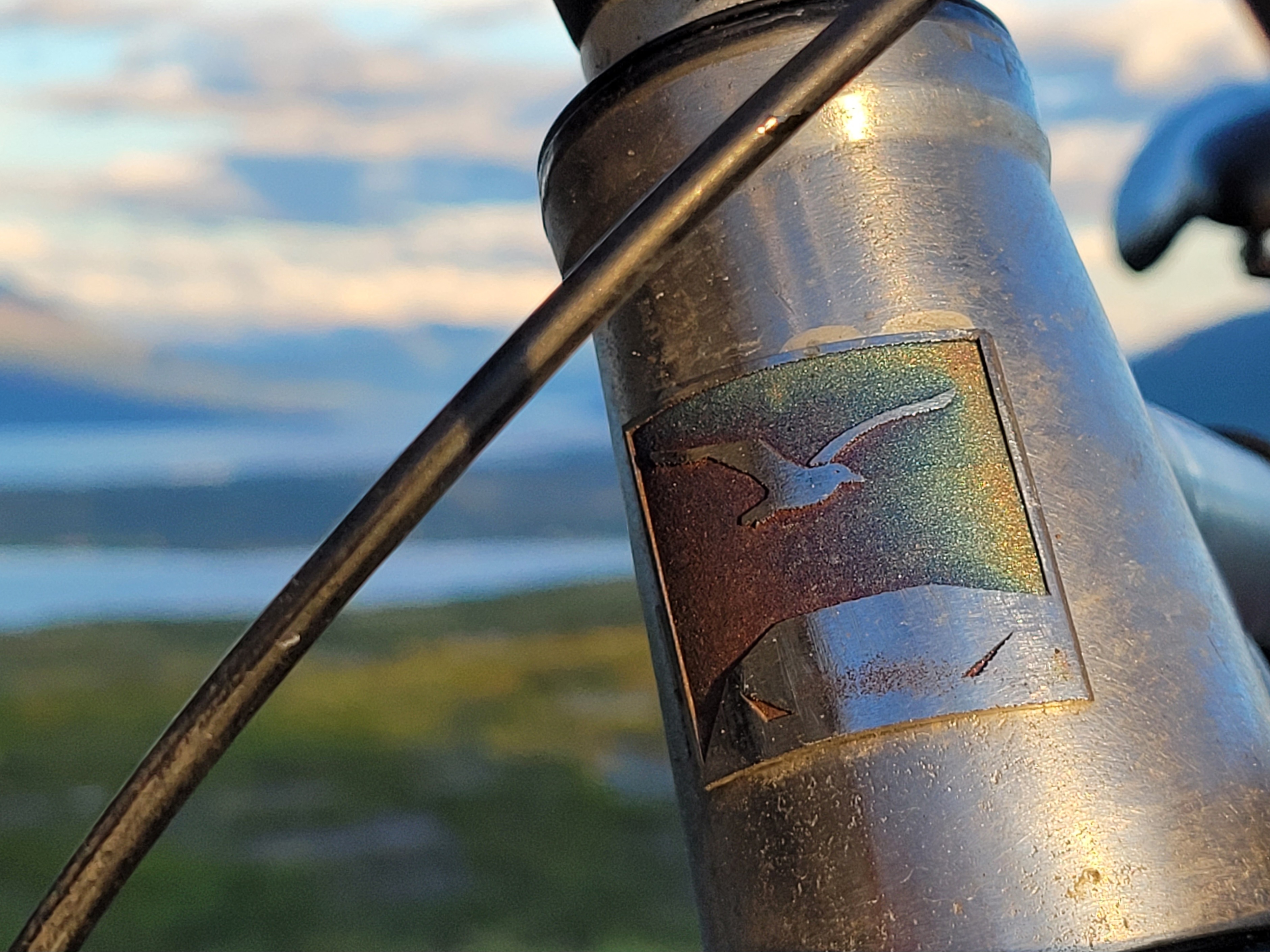
And... there is no headtube badge modelled in - but I created one later.

Made with Mobirise
Website Maker